Rockwell Automation Publication 750-IN017B-EN-P - June 2018 7
PowerFlex 750-Series Service Cart Frames 8…10 Conversion Kit
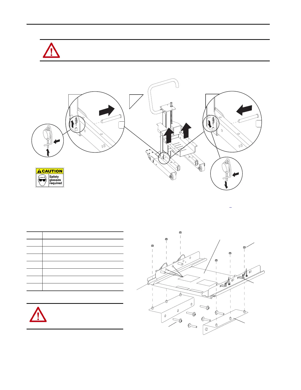
4. Use the pliers to remove the cotter keys from the left and right carriage assembly clevis pins. Then remove the clevis pins.
5. Remove the bridge floor from the carriage assembly.
6. Insert the left and right, carriage assembly clevis pins into their original location and attach the cotter keys See step 4
for more information.
Service Cart Frames 8…10 Conversion
Kit Components
ATTENTION: Avoid personal injury. Wear goggles to protect your eyes when removing cotter keys.
Avoid personal injury and equipment damage. The bridge span is loosely attached to the bridge floor, take precautions when removing the bridge floor
to ensure that the bridge span does not break free or fall causing personal injury.
Item Description
1 Frames 8…10 bridge plate
2 M8 nuts (three left and three right)
3 Anchor pins (two left and two right)
(1)
(1) This item comes pre-attached to the frames 8…10 bridge plate.
4 Base extender (one left and one right)
5 M10 bolts (three left and three right)
6 Position indicators (A,B,C locations; six left and six right)
7 Cart lock safety clips (one left one right)
(1)
ATTENTION: The PowerFlex 750-Series
service cart frames 8…10 conversion kit
weighs approximately 32 kg (70 lb) and
requires two persons to lift.
2x
4
5
6
2x
To align the holes, pull the wheel mount up.
To remove, pull the cotter key toward you and then push up.
6 (x12)
7 (x2)
5 (x6)
4 (x2)
3 (x4)
2 (x6)
1

 Loading...


