30 Rockwell Automation Publication PFLEX-AP005A-EN-P - October 2010
Chapter 1 Drive Selection Considerations
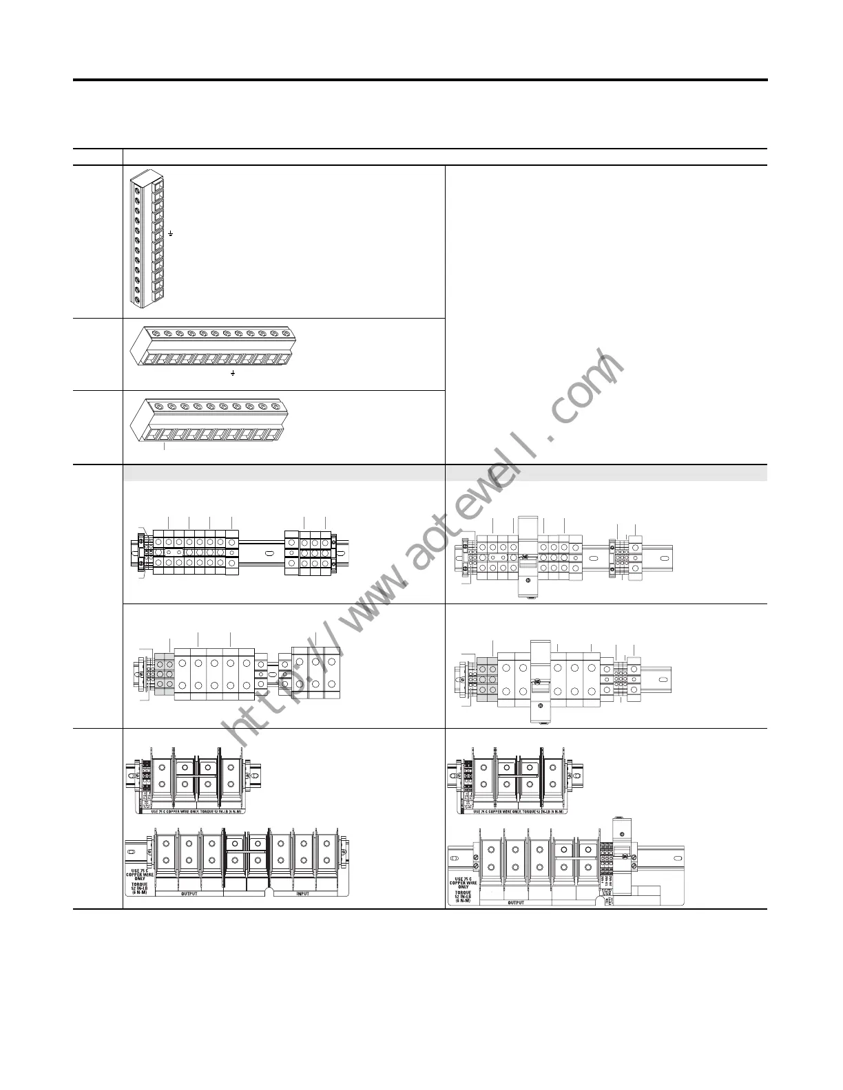
Table 9 - PowerFlex 700 Drive Power Terminals
Frame Terminal Block
0 & 1
2
3 & 4
(1)
AC Input DC Input
5
(1)
75 Hp, Normal Duty 75 Hp, Normal Duty
100 Hp, Normal Duty 100 Hp, Normal Duty
6
(1)
125…200 Hp, Normal Duty 125…200 Hp, Normal Duty
(1) BR1 and BR2 terminals will be present only on Frame 4…6 drives ordered with the Brake IGBT option.
BR1
BR2
DC+
DC–
PE
U (T1)
V (T2)
W (T3)
R (L1)
S (L2)
T (L3)
T
(L3)
S
(L2)
R
(L1)
W
(T3)
V
(T2)
U
(T1)
PEDC–DC+BR2BR1
T
(L3)
S
(L2)
R
(L1)
W
(T3)
V
(T2)
U
(T1)
DC–DC+
BR2*
BR1*
T/L3
S/L2
R/L1
PE
PE
W/T3
V/T2
U/T1
DC–
DC+
BR1*
DC+
BR2*
PS–
PS+
PE
W/T3
V/T2
U/T1
DC–
DC+
BR1*
DC+
BR2*
PS–
PS+
240V
120V
0V
PE
(AC voltage)
W/T3
PE PE
V/T2
U/T1
DC–
BR1*
DC+
DC+
BR2*
PS–
PS+
T/L3
S/L2
R/L1
DC+ DC– V/T2
PE
BR1*
DC+
BR2*
PS–
PS+
U/T1 W/T3
240V
120V
0V
PE
(AC voltage)
U
T1
DC–DC+BR1*BR2*
V
T2
W
T3
R
L1
S
L2
T
L3
PE PE
U
T1
DC–DC+
V
T2
W
T3
PE PE
BR1*BR2*

 Loading...


