Rockwell Automation Publication 750-PM101B-EN-P - April 2022 13
Chapter 1 Overview
3. De-energize 240V control power (D).
4. Leave the Control Power switches (E) for the Common Bus Inverters in
the ‘On’ position when the drive system is not in operation.
5. Leave the DC Precharge switches (F) for the Common Bus Inverters in
the ‘On’ position when the drive system is not in operation. This step is
not required for Common Bus Inverters without DC Precharge.
Systems with 24V Auxiliary Power and with Separate 240V Control
Power
Bus supplies ordered without the –C1 Control Transformer option require
separate 240V control power.
Energize
Energize the product in the following sequence:
1. Leave 24V auxiliary power (C) energized when the drive is not in
operation. This keeps up the control and communication.
2. Leave the Control Power switches (E) for the Common Bus Inverters in
the ‘On’ position when the drive system is not in operation.
3. Leave the DC Precharge switches (F) for the Common Bus Inverters in
the ‘On’ position when the drive system is not in operation. This step is
not required for Common Bus Inverters without DC Precharge.
IMPORTANT
Step 3, de-energize 240V control power is required. If three-phase
power is de-energized and re-energized while 240V control power
stays energized, Common Bus Inverter non-resettable functional
safety faults result. To clear these faults, de-energize and re-
energize 240V control power.
IMPORTANT
This procedure assumes that 24V auxiliary power was not removed when
the product was de-energized. If you are conducting an initial power-up,
or if 24V auxiliary power was removed, only apply 24V auxiliary power as
the final step in the Energize sequence.
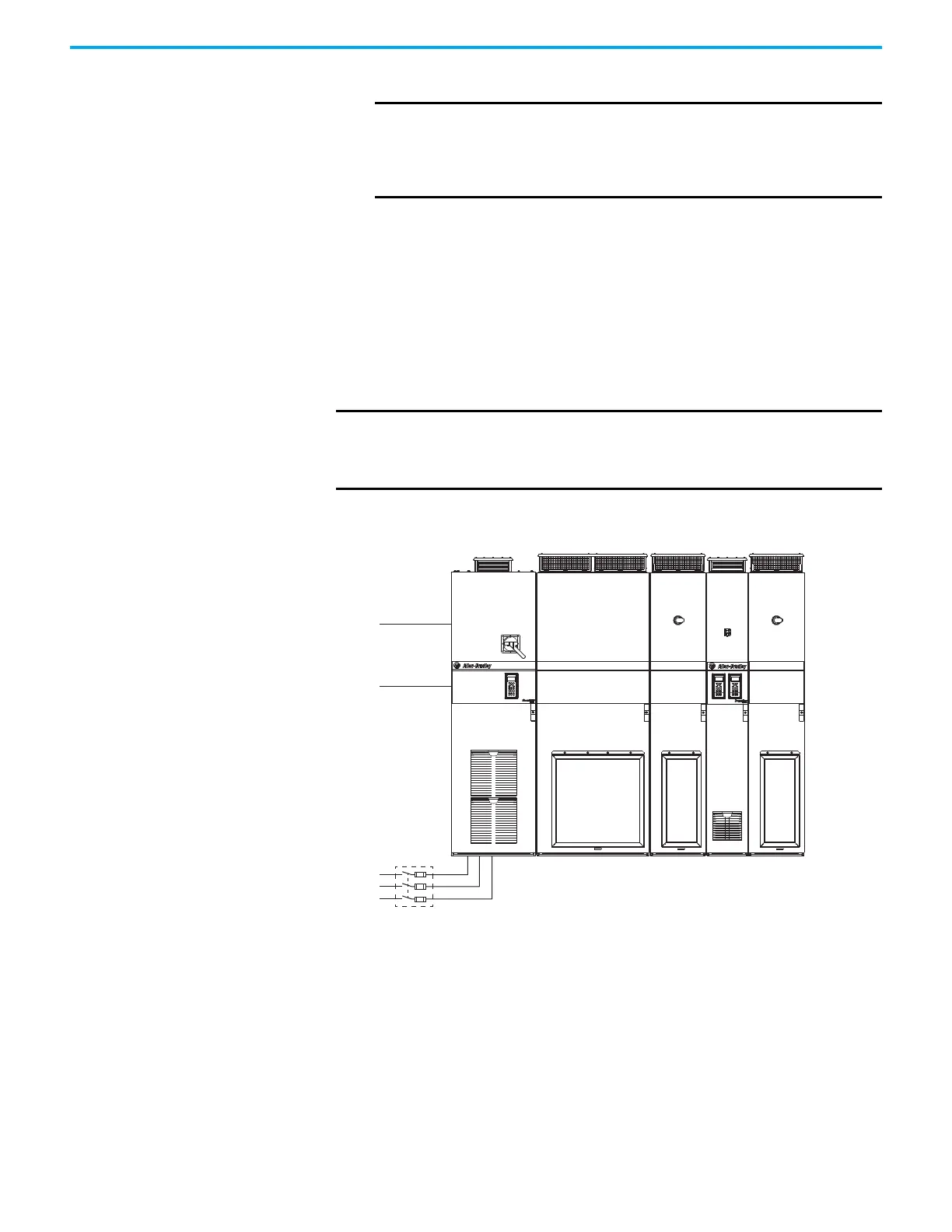
(D)
240V Control Power
(A)
(B)
Three-phase Power
(F) (F)
(E)
24V Auxiliary Power
(C)
Input Bay Power Bay Power Bay Power BayControl
Bay

 Loading...


