30 Rockwell Automation Publication 750-PM101B-EN-P - April 2022
Chapter 3 PowerFlex 755T Control Block Diagrams
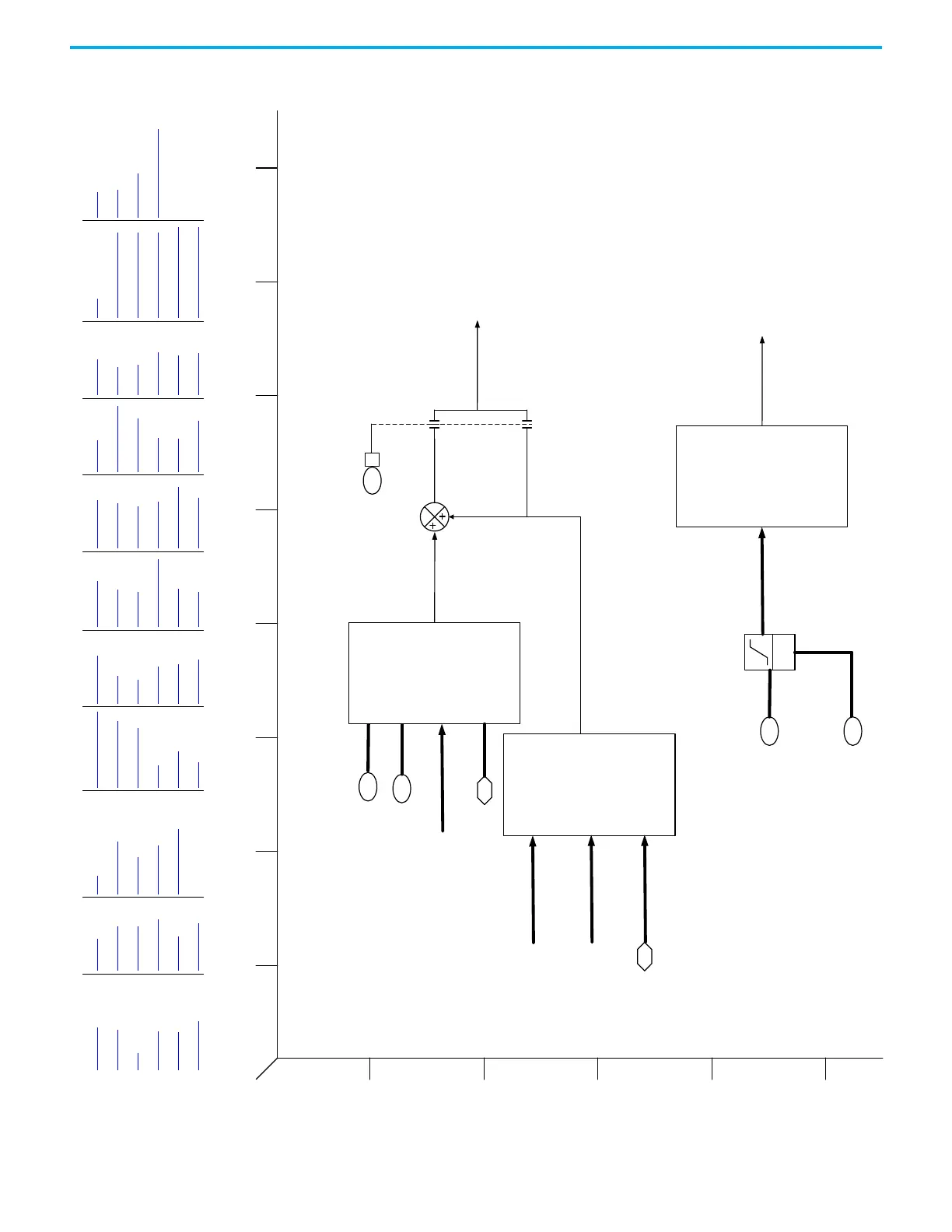
Figure 9 - Reactive Power Control
1
2
3
4
5
6
BA
D
C
FHEG
I
Reactive Power Control (VarCtrl)
KVAR Rate Limit
Rate
Limit
70
KVAR Ref
69
Reference Reactive Current
Calculation
CurrPwrLmt [F5}
VoltRefGen [C5}
0
1
VarDCBAdjDis
40 3
82
BusAutoAdjReg Kp
83
BusAutoAdjReg Ki
BusRefAutoAdjReg
Vq
Metering [D1]
Metering [D5]
3
Port 0,DC Bus Volts
BusRefAutoAdjCalculation
Vq
Metering [D1]
SourceImpedance
LscData [C5]
67Active Cur Cmd
Overview VarCtrl PFC Vector Overview PRef Move Prof Ind 2 VelRefCAM Ld Obs Cur IPM MOP Logic
Metering DroopCtrl CurPwrLmt Freq Overview PRef2 Roll Psn VRef Vect Friction Comp Proc 1 22Series IO Digital Invert
PLL DroopCtrl CurrCtrl CBI Metering PReg Spindle Ref Move Trq RefCAM Proc 2 22Series IO Digital Motor I2T
PwrLoss VoltRefGen LscCtrlCfg Fdbk Psn PLL VRef Overview VReg Vect Trq Ref AntiSway 11-Series IO Digital High Speed Wizard
LscData VoltCtrl DriveDerating Homing Psn CAM VRef Sel Trq Overview Trq Filt Oil Well 1 22-Series IO Analog
CurRefGen DCBusObs PRef1 Prof Ind 1 VRef All Trq Ref Sel Cur IM SPM Oil Well 2 22-Series IO Analog VarCtrl

 Loading...


