Rockwell Automation Publication 750-PM101B-EN-P - April 2022 43
Chapter 3 PowerFlex 755T Control Block Diagrams
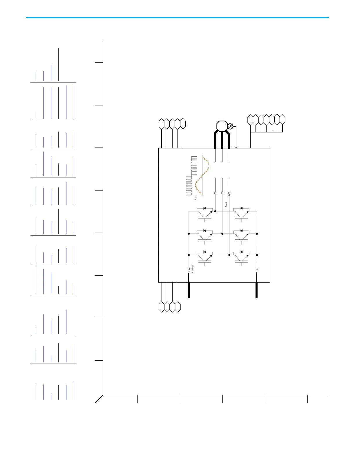
Figure 22 - CBI Metering
1
2
3
4
5
6
BA
D
C
FHEG
I
CBI Metering Signals (CBI Metering)
AC
Motor
Common Bus Inverter (CBI)
U Motor Phase
V Motor Phase
W Motor Phase
Digital
Encoder
Option
DC - Bus
DC + Bus
Motor Side Power Structure
1914
VRef Commanded
Command Signals
1933
2073
1731
VRef Final
Trq Commanded *
Position Command **
* Flux Vector Only
** Flux Vector with Encoder Only
1
Output Frequency
Output Signals
2
3
4
Output Voltage
Output Current
Output Power
5
Output Pwr Factr
8
Torque Cur Fb
Feedback Signals
9
11
13
Flux Cur Fb
Motor Voltage Fb
DC Bus Memory
1044
Motor Vel Fb –
for Freq control modes, this is ltered VRef Final
1745
1746
Position Actual **
Position Fb **
Overview VarCtrl PFC Vector Overview PRef Move Prof Ind 2 VelRefCAM Ld Obs Cur IPM MOP Logic
Metering DroopCtrl CurPwrLmt Freq Overview PRef2 Roll Psn VRef Vect Friction Comp Proc 1 22Series IO Digital Invert
PLL DBC CurrCtrl CBI Metering PReg Spindle Ref Move Trq RefCAM Proc 2 22Series IO Digital Motor I2T
PwrLoss VoltRefGen LscCtrlCfg Fdbk Psn PLL VRef Overview VReg Vect Trq Ref AntiSway 11-Series IO Digital High Speed Wizard
LscData VoltCtrl DriveDerating Homing Psn CAM VRef Sel Trq Overview Trq Filt Oil Well 1 22-Series IO Analog
CurRefGen DCBusObs PRef1 Prof Ind 1 VRef All Trq Ref Sel Cur IM SPM Oil Well 2 22-Series IO Analog CBI Metering

 Loading...


