98 Rockwell Automation Publication 750-PM101B-EN-P - April 2022
Chapter 4 Troubleshooting
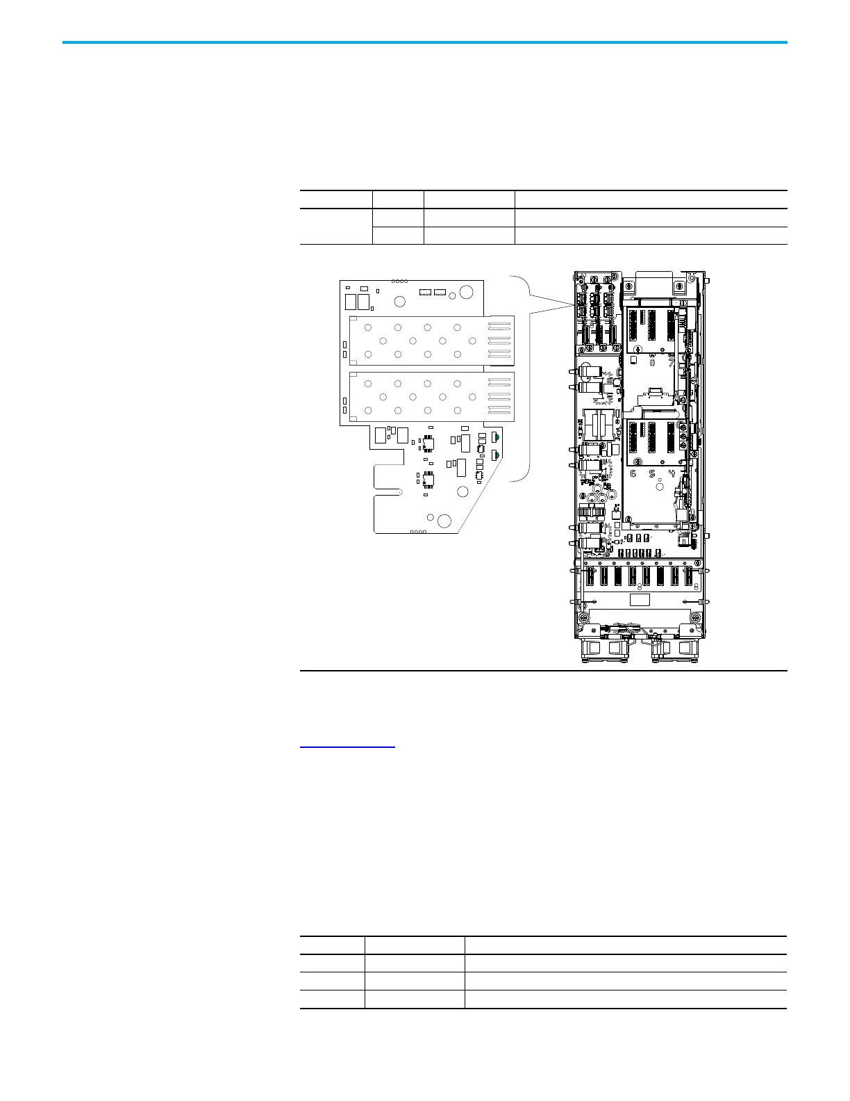
Fiber-optic Transceiver Circuit Board Status Indicators
PowerFlex 755T fiber-optic transceiver circuit boards use status indicators to
report conditions. The fiber-optic transceiver circuit boards plug into edge
connectors on the fiber interface circuit board in the control pod assembly of
frame 7…15 drives and bus supplies.
Setting Factory Defaults The PowerFlex 20-HIM-A6/-C6S HIM User Manual, publication
20HIM-UM001
, provides detailed instructions on using Human Interface
Module capabilities, including, setting the PowerFlex 750-Series drive to
factory settings.
The following tables list the parameters that are not reset when Set Defaults
‘Most’ is executed.
Also, the High Speed Trending configuration and the internal date and time
properties are not reset by this operation.
Name Color State Description
DS1, DS2
Green Flashing Fiber connection is online.
Red Flashing Fiber connection is offline.
DS2
DS1
Control Pod Assembly
Port 0: Product Config File, Preferences Group
Number Display Name Full Name
30 Access Level User Access Level
31 Language Display Language
46 Velocity Units Velocity Units

 Loading...


