Rockwell Automation Publication 750-PM101B-EN-P - April 2022 97
Chapter 4 Troubleshooting
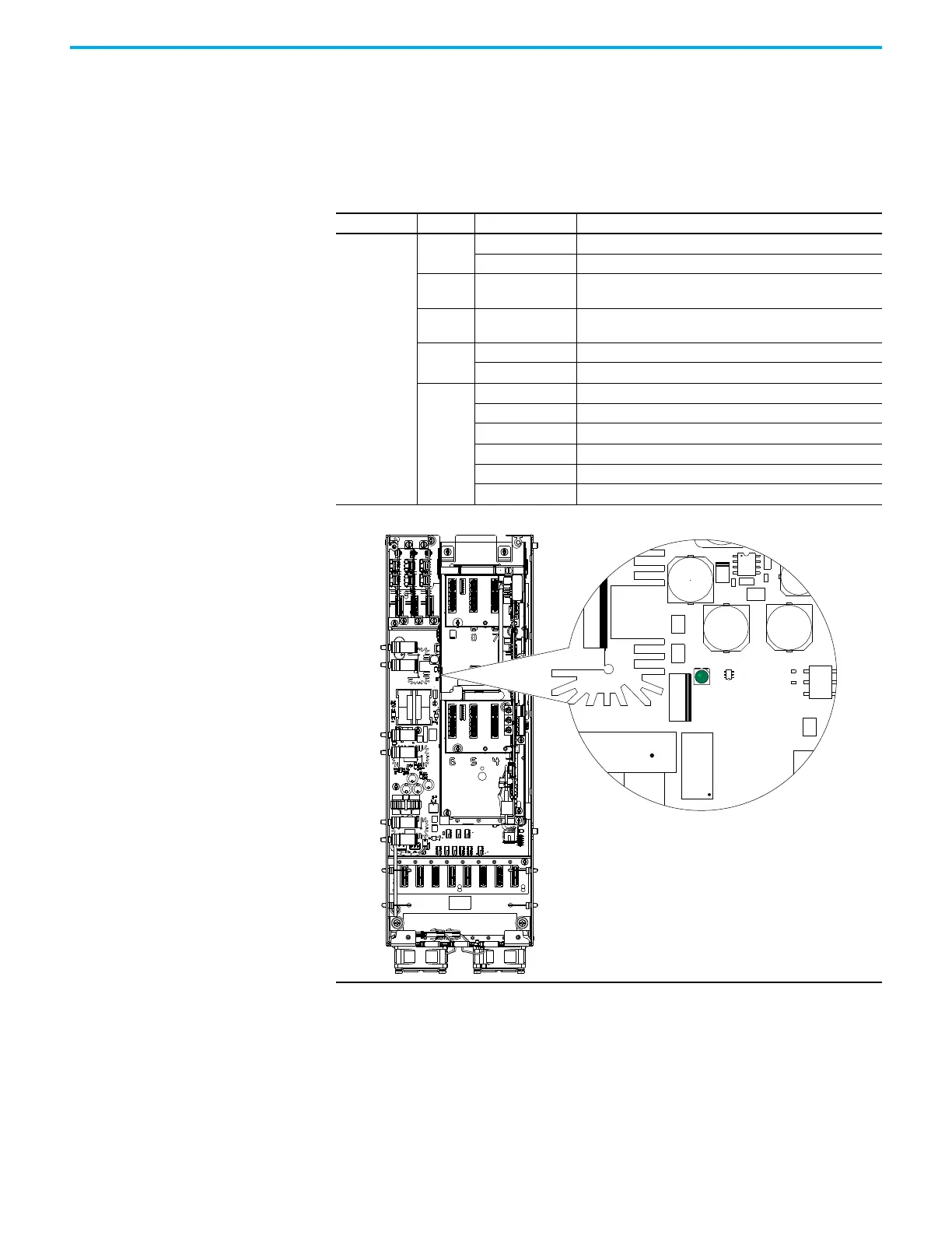
Fiber-optic Interface Circuit Board Status Indicator
The PowerFlex 755T fiber-optic interface uses a status indicator to report
conditions. The fiber-optic interface circuit board is mounted on the rear panel
of the control pod assembly and is used with frame 7…15 drives and bus
supplies.
Name Color State Description
DS1
Green
Flashing at 2 Hz Active mode in process.
Flashing at 0.5 Hz Update in process.
Green /
Yellow
Flashing Alternately Login mode in process.
Green /
Red
Flashing Alternately Erase in process.
Yellow
Flashing at 2 Hz Loopback fiber test mode is in process.
Flashing at 0.5 Hz Boot mode is in process.
Red
Blink 2 Count Clock fault
Blink 3 Count Firmware fault
Blink 4 Count FLEXBUS fault
Blink 5 Count PRGM fault
Blink 6 Count FPGA PRGM fault
Blink 7 Count SFLASH PRGM fault

 Loading...


