Rockwell Automation Publication 750-PM101B-EN-P - April 2022 95
Chapter 4 Troubleshooting
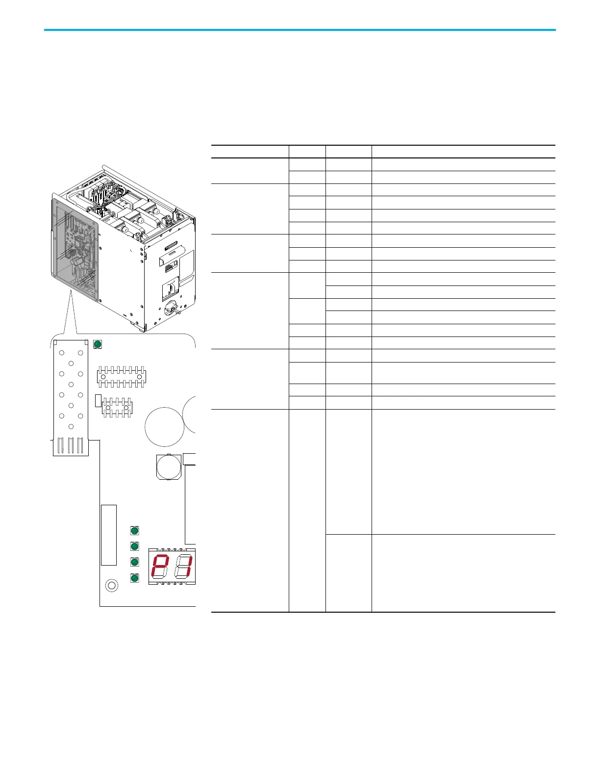
DC Precharge Circuit Board Status Indicators
The PowerFlex 755T DC precharge module uses status indicators and a 7-
segment display to report conditions. The DC precharge circuit board is
located behind a transparent panel on the left side of the DC precharge module
chassis. The DC precharge circuit board status indicators are not visible while
installed in a DC precharge module.
Name Color State Description
DS7 (DC Precharge)
Green Flashing Fiber connection is online.
Red Flashing Fiber connection is offline.
DS2 (240V AC)
Green Steady 240V AC Okay
Yellow Steady 240V AC Low Alarm
Red Flashing 240V AC Loss Fault
Unlit Off 240V AC Loss Alarm
DS3 (Communications)
Green Steady Fiber connection is online.
Yellow Flashing Communications Loss
Unlit Off Inactive
DS4 (DC Precharge)
Green
Steady Precharge Done (Molded case switch is closed.)
Flashing Molded case switch is closing.
Yellow
Steady Molded case switch is opening.
Flashing Not Ready
Red Flashing Molded case switch opened.
Unlit Off Ready
DS5 (Firmware Status)
Green Steady No faults or alarms are present.
Green /
Red
Flashing
Alternately
Update in progress.
Yellow Steady Alarm is present.
Red Flashing Fault is present.
7-Segment Display Red
Steady
Normal Operation
• At powerup, the display indicates the major firmware revision
number, the minor revision number, and the build number for 1
second each.
• After powerup is complete, the display indicates the number
that is assigned to the module by the main control board.
(Shown: P1 = Precharge 1)
Alarms
• When an alarm condition exists, the display indicates the alarm
code.
• If there are multiple alarm codes, the display cycles through the
codes and displays each code for 2 seconds.
Flashing
Faults
• When a fault condition exists, the display indicates the fault
code.
• If there are multiple fault codes, the display cycles through the
codes and displays each code for 2 seconds.
• If the device is faulted, the display only indicates fault codes.
Alarm codes are omitted.
DS7
DS2
DS3
DS4
DS5
7-Segment Display
DC Precharge Module

 Loading...


