66 Rockwell Automation Publication 520-UM001I-EN-E - July 2016
Chapter 2 Start Up
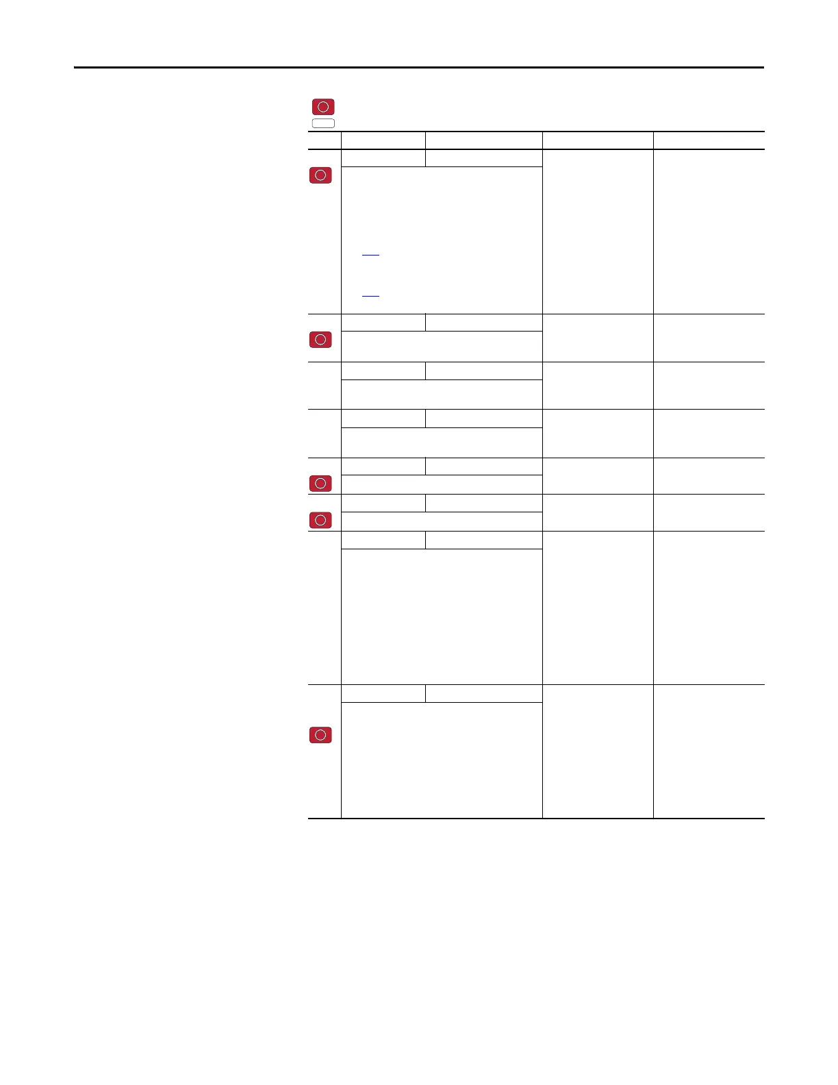
P039 [Torque Perf Mode] 0/4 0 = “V/Hz”
1 = “SVC”
2 = “Economize”
3 = “Vector”
(1)
4 = “PM Control”
(1)(2)(3)
1
Selects the motor control mode.
(1) Setting is specific to PowerFlex 525 drives only.
(2) Setting is available in PowerFlex 525 FRN 5.xxx and
later.
(3) When P039 [Torque Perf Mode] is set to 4 and
A535
[Motor Fdbk Type] is set to 0, 1, 2 or 3, the drive
is in open loop PM motor control mode.
When P039 [Torque Perf Mode] is set to 4 and
A535
[Motor Fdbk Type] is set to 4 or 5, the drive is in
closed loop PM motor control mode.
P040 [Autotune] 0/2 0 = “Ready/Idle”
1 = “Static Tune”
2 = “Rotate Tune”
0
Enables a static (not spinning) or dynamic (motor
spinning) autotune.
P041 [Accel Time 1] 0.00/600.00 s 0.01 s 10.00 s
Sets the time for the drive to accel from 0 Hz to
[Maximum Freq].
P042 [Decel Time 1] 0.00/600.00 s 0.01 s 10.00 s
Sets the time for the drive to decel from [Maximum
Freq] to 0 Hz.
P043 [Minimum Freq] 0.00/500.00 Hz 0.01 Hz 0.00 Hz
Sets the lowest frequency the drive outputs.
P044 [Maximum Freq] 0.00/500.00 Hz 0.01 Hz 60.00 Hz
Sets the highest frequency the drive outputs.
P045 [Stop Mode] 0/11 0 = “Ramp, CF”
(1)
1= “Coast, CF”
(1)
2 = “DC Brake, CF”
(1)
3 = “DCBrkAuto,CF”
(1)
4= “Ramp”
5= “Coast”
6= “DC Brake”
7= “DC BrakeAuto”
8= “Ramp+EM B,CF”
(1)
9= “Ramp+EM Brk”
10 = “PointStp,CF”
(1)
11 = “PointStop”
0
Stop command for normal stop.
Important: I/O Terminal 01 is always a stop input.
The stopping mode is determined by the drive
setting.
Important: The drive is shipped with a jumper
installed between I/O Terminals 01 and 11. Remove
this jumper when using I/O Terminal 01 as a stop or
enable input.
(1) Stop input also clears active fault.
P046,
P048,
P050
[Start Source 1] 1/5 1 = “Keypad”
(1)
2 = “DigIn TrmBlk”
(2)
3 = “Serial/DSI”
4 = “Network Opt”
5 = “Ethernet/IP”
(3)
P046 = 1
P048 = 2
P050 = 3 (PowerFlex 523)
5 (PowerFlex 525)
Sets the default control scheme used to start the
drive unless overriden by P048 [Start Source 2] or
P050 [Start Source 3].
(1) When active, the Reverse key is also active unless
disabled by A544 [Reverse Disable].
(2) If “DigIn TrmBlk” is selected, ensure that the digital
inputs are properly configured.
(3) Setting is specific to PowerFlex 525 drives only.
= Stop drive before changing this parameter.
= Parameter is specific to PowerFlex 525 drives only.
No. Parameter Min/Max Display/Options Default

 Loading...


