EN
58
6.2 Electrical connections
A switch or an omnipolar cut-off switch with a contact opening of at least 3 mm must be
installed on the mains power line; put the cut-off switch in OFF position and disconnect any
buffer batteries before performing any cleaning or maintenance operations.
Ensure that an adequate residual current circuit breaker with a 0.03 A threshold and a suitable
overcurrent cut-out are installed upstream the electrical installation in accordance with best
practices and in compliance with applicable legislation.
For power supply, use a H07RN-F 3G1.5 type electric cable and connect it to the terminals L
(brown), N (blue),
(yellow/green), located inside the control panel box.
Strip the insulation from the ends of the power cable wires which will be connected to the
YJWRNSFQXJJWJK&ܪLFSIXJHZWJYMJHFGQJ\NYMYMJHFGQJWJYFNSJW
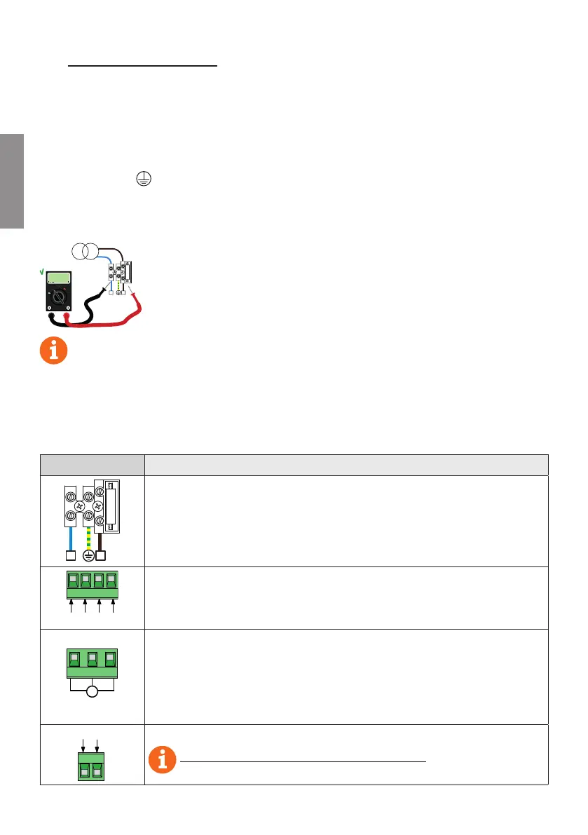
Measure the voltage on the primary mains power connection with a tester.
A
V
V
A
+-COM
220÷230
N L
FUSE
TRANSFORMER
For the Brushless automation system to function correctly, the mains
power voltage must be:
- 230Vac ±10% for the B70/1DCHP control unit.
- 115Vac ±10% for the B70/1DCHP/115 control unit.
.KYMJIJYJHYJI[FQZJITJXSTYHTRUQ^\NYMYMJFGT[JXUJHNܪJI[FQZJXTWNX
STYXYFGQJYMJFZYTRFYNTSX^XYJRRF^349TUJWFYJJKܪHNJSYQ^
Connections to the electrical distribution network and to any other low-voltage conductors
in the external section to the electrical panel must be on an independent path and
separate from the connections to the command and safety devices (SELV = Safety Extra Low
Voltage).
Make sure that the mains power conductors and the accessory wires (24 V) are separated.
The cables must be double insulated, strip them near the relevant connection terminals and
lock them with clamps (not supplied).
DESCRIPTION
FUSE
N L
Mains power supply 230 Vac ±10% (115 Vac ±10%) connection.
Fuse 5x20 T2A.
SEC2 SEC1
Secondary transformer input for 26 V AC motor power (SEC1) and for 19 V power to logical
control and peripheral devices (SEC2).
N.B.: Ready wired in factory by ROGER TECHNOLOGY.
X-Y-Z
Y
X
M
Z
Connection to ROGER brushless motor.
Connecting B72/BRAKE/2 HTSYWTQQJWKTW',-NLM8UJJI[JWXNTSXXJJܪL
N.B.: Ready wired in factory by ROGER TECHNOLOGY.
Warning! If the motor wires become disconnected from the terminal board, after reconnect-
ing correctly, the travel must be acquired again as described in chapter 11.
BATTERY
-+
Connection to B71/BCHP GFYYJW^PNYXJJܪL
See instructions for B71/BCHP for further information.
 Loading...