Figures Power Supply NGMO
Version 4.00 / 07-2004 3
Figures
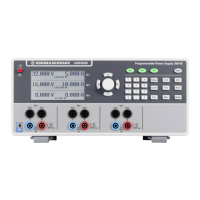
Fig. 3-1 NGMO2, Front view 3-2
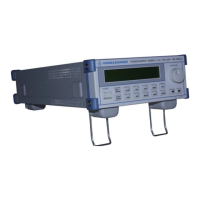
Fig. 3-2 NGMO2, Rear view 3-3
Fig. 3-3 NGMO2, Pin codes 3-7
Fig. 3-4 Circuit diagram: Mobile phone connected to the NGMO2 3-8
Fig. 4-1 NGMO2, Operation elements on the control panel 4-1
Fig. 4-2 Four-wire sense connection 4-20
Fig. 4-3 Local sense connections 4-21
Fig. 4-4 Sample values 4-24
Fig. 4-5 Pre-trigger and post-trigger acquisition 4-25
Fig. 4-6 Measurement repetition 4-26
Fig. 4-7 Status model structure 4-29
 Loading...