Instrument Tour
R&S
®
RTP
21Getting Started 1337.9946.02 ─ 05
5 = Analysis keys
6 = Navigation controls
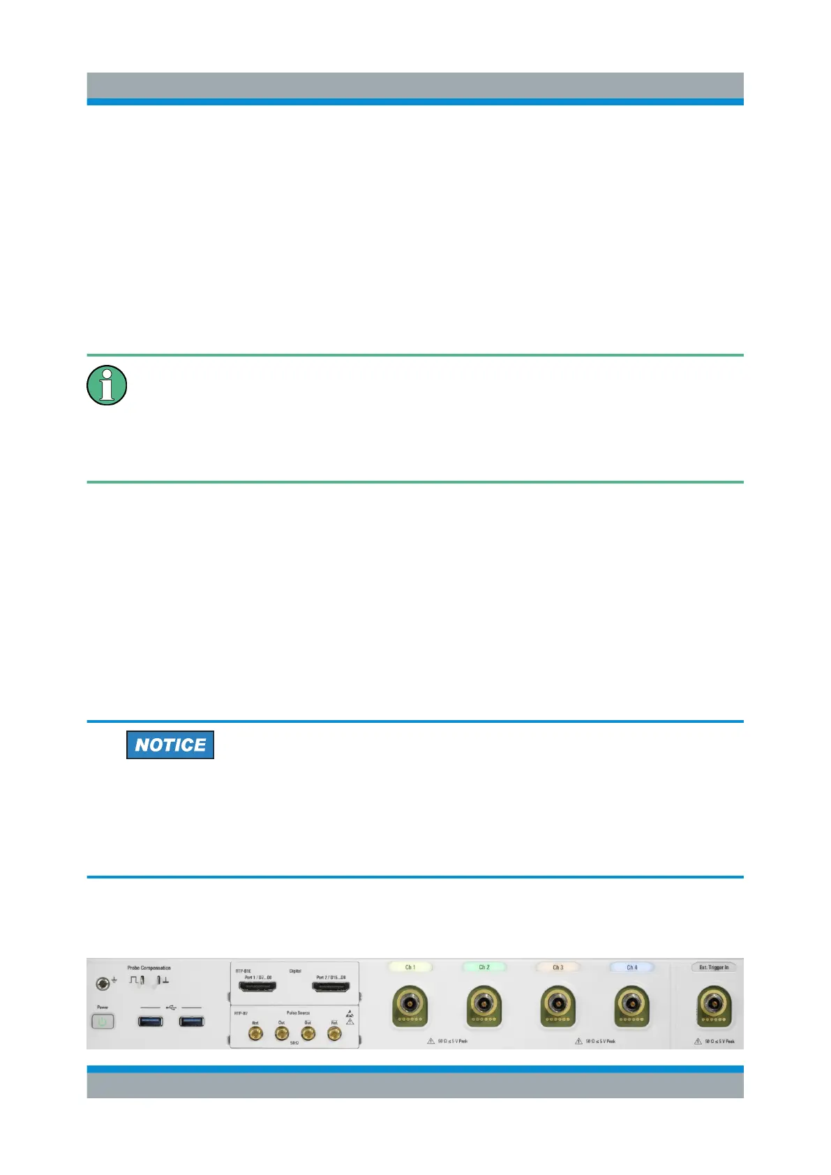
7 = External trigger input
8 = Vertical controls
9 = Input channels
10 = Two option slots for R&S RTP-B1 (MSO) or R&S RTP-B1E (for R&S RT-ZVC) , R&S RTP-
B6 (waveform generator), R&S RTP-B7 (pulse source)
11 = USB connectors
12 = Connectors for probe compensation and grounding
13 = [Power] key
Three of the mentioned options can be installed in one R&S RTP - two at
the front panel, and one at the rear panel. Each option can be installed
once only. To ensure correct installation and calibration, installation is done
only at Rohde & Schwarz service centers. See also: "Option slot"
on page 26.
Channel inputs and external trigger input
The R&S RTP has four channel inputs to connect the input signals, and an exter-
nal trigger input to control the measurement by an external signal.
The input connectors are provided with a special Rohde & Schwarz active probe
interface, and they are BNC compatible. Thus, the instrument can automatically
detect active probes that have the Rohde & Schwarz probe interface.
The input impedance of the inputs is 50 Ω.
Risk of instrument damage
The instrument is not rated for any measurement category.
Make sure that the input voltage on channel inputs and the external trigger
input does not exceed 5 V peak at 50 Ω input impedance.
The keys and controls are described in Chapter 4.3, "Keys and Controls",
on page 26. The following connectors are available at the front panel:
Front Panel

 Loading...


