7
3-1 Setting Up and Connection
3 Basic Operation
Ground the unit with the ground
wire.
Failure to do so may result in risk of
electrical shock in the even of a mechanical
problem
Do not use with any electrical power
supply that does not meet the
ratings displayed on the unit.
Use with any other power supply may lead
to fire or electrocution.
Install on a stable surface.
Failure to do so
may result in
falling of the unit,
leading to injury.
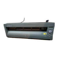
Do not try to pick up or move the CM-24/12 by grasping the top area of the unit. Be sure to use both hands to
grip the CM-24/12 securely on the left and right sides.
Never install this unit in any of the following situations, as it could result in damage:
Places where the installation surface is unstable or not level.
Places with excessive electrical noise.
Places with excessive humidity or dust.
Places with poor ventilation, because the CM-24/12 generates considerable heat during operation.
Places with excessive vibration.
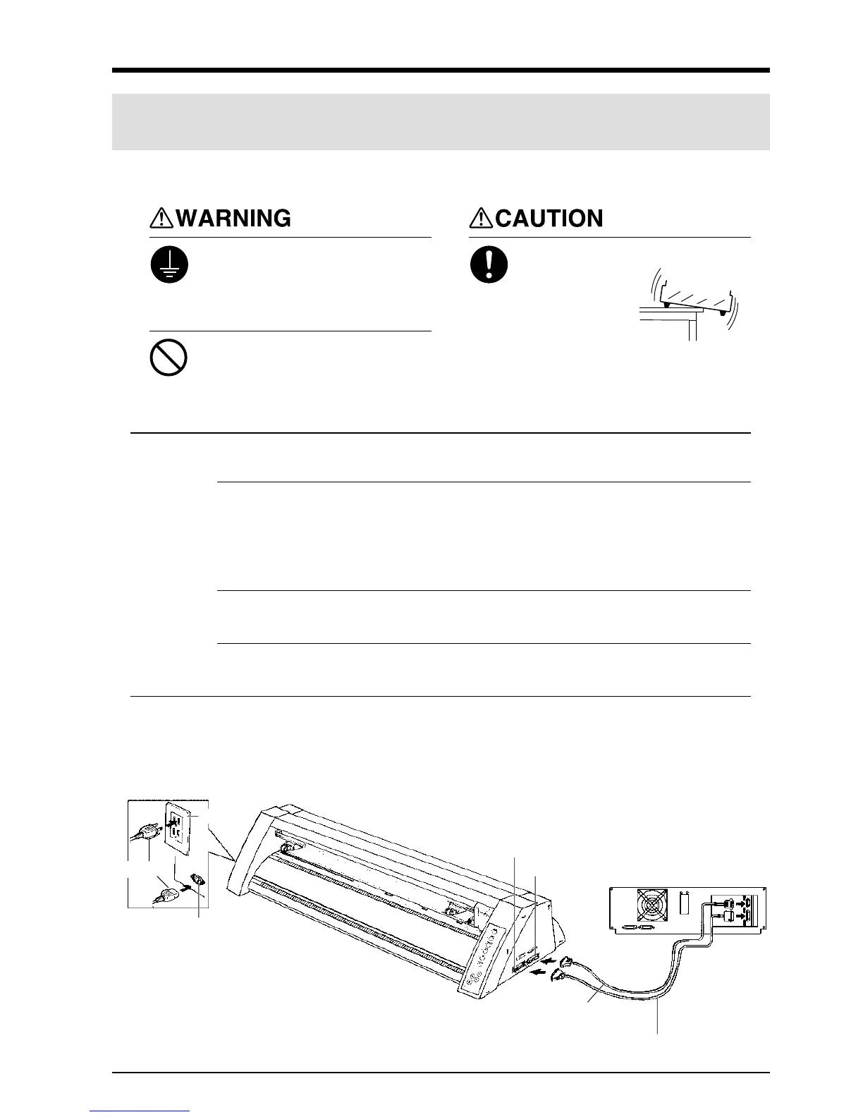
Connect the cable to either the parallel or the serial port. Be sure that the power to both the computer and the
main unit is switched off when connecting the cable.
NOTICE
Securely connect the power cord, computer I/O cable and so on so that they will not be unplugged and cause
failure during operation. Doing so may lead to faulty operation or breakdown.
Serial connector
or
Parallel connector
When the CM-24/12 is connected to the computer via the
serial port, the communication parameters (Baud, Data, Parity,
Stop, etc.) for the CM-24/12 need to match the port settings on
the computer. Use the DIP switches on the right-hand side of
the CM-24/12 to make these settings. Refer to "3-2 DIP
Switch Settings" to make the correct settings.
Serial interface cable
(Connect to the serial input port.)
or
Parallel interface cable (Connect to the parallel input port.)
* Cables are available separately. One which you are sure matches
the model of computer being used should be selected.
Parallel input connector
Serial input connector
Power connector
Power cord
Power
outlet
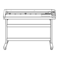
Make sure the unit is placed on a stable, sturdy surface.
When arranging setup space for the CM-24, make sure you have a space that is at least 950 mm (37-7/16") wide, 500 mm (19-11/16") in
depth, and 230 mm (9-1/16") in height. For the CM-12, a space that is at least 650 mm (25-5/8") wide, 500 mm (19-11/16") in depth, and
230 mm (9-1/16") in height.
Since the material moves during cutting, make sure there is nothing that can block the material at both front and rear.

 Loading...