EasyManua.ls Logo

Roland Color Camm Pro PC-60 - User Manual

Roland Color Camm Pro PC-60
100 pages
Print Icon
To Next Page IconTo Next Page
Loading...
SERVICE NOTES
Unauthorized copying or transferral, in whole or in part, of this manual is prohibited.
Copyright © 1998 ROLAND DG CORPORATION
Windows is registered trademark or trademark of Microsoft Corporation in the United States and/or other countries.
PC-60
R1-980203
First Edition
PC-60 '98.Jan.DE1
Printed in Japan
1 Structure & Spare Parts
1-1 COVERS .......................................................................................1
1-2 FRAME (1) ....................................................................................2
1-3 FRAME (2) ....................................................................................4
1-4 CHASSIS ......................................................................................6
1-5 THERMAL CARRIAGE .................................................................7
1-6 TOOL CARRIAGE .........................................................................7
1-7 STAND ..........................................................................................8
1-8 ACCESSORIES ............................................................................8
2 Electrical Section
2-1 WIRING MAP ................................................................................9
2-2 MAIN BOARD ASS'Y .................................................................. 10
2-3 OTHER CIRCUIT BOARDS ........................................................ 17
3 Replacement of Main Parts
3-1 HEAD CARRIAGE ASSEMBLY_QUICK REPLACEMENT ......... 19
3-2 HEAD CARRIAGE ASSEMBLY_REPLACEMENT .....................22
3-3 TOOL CARRIAGE ASSEMBLY_REPLACEMENT .....................25
3-4 PLATEN DAMPER_REPLACEMENT ......................................... 26
3-5 HEAD LEVER_FIXING ............................................................... 27
3-6 CARTRIDGE HOLDER ARM_REPLACEMENT .........................29
3-7 PINCH ROLLER_REPLACEMENT ............................................. 32
3-8 WIRE_REPLACEMENT .............................................................. 35
3-9 MOTOR_FIXING .........................................................................38
4 Adjustment
4-1 Special Tool ................................................................................ 39
4-2 Service Mode .............................................................................. 40
4-3 Factory Mode .............................................................................. 41
4-4 Faunction Mode .......................................................................... 43
4-5 HOW TO UPGRADE FIRMWARE .............................................. 45
4-6 TOOL HEIGHT ADJUSTMENT ................................................... 46
4-7 TOOL PRESSURE ADJUSTMENT ............................................ 48
4-8 HEAD VOLTAGE ADJUSTMENT ............................................... 51
4-9 AUTO THERMAL HEAD DENSITY ADJUSTMENT ................... 53
4-10 MANUAL THERMAL HEAD DENSITY ADJUSTMENT .............. 57
4-11 HEAD POSITION ADJUSTMENT 1 ............................................ 61
4-12 HEAD POSITION ADJUSTMENT 2 ............................................ 63
4-13 PRINT/CUT OFFSET ADJUSTMENT .........................................65
4-14 CARTRIDGE POSITION ADJUSTMENT .................................... 67
4-15 CMYK SENSING CHECK ........................................................... 70
4-16 GRIT COMPENSATION ............................................................. 72
4-17 WIRE TENSION ADJUSTMENT .................................................75
4-18 STITCHING ADJUSTMENT ........................................................ 77
4-19 GRIT ECCENTRICITY ADJUSTMENT .......................................80
5 Supplemental Information
5-1 OPERATIONAL SEQUENCE ..................................................... 85
5-2 SENSOR MAP ............................................................................86
6 Troubleshooting
6-1 PRINTING ................................................................................... 87
6-2 CUTTING .................................................................................... 89
6-3 OTHERS .....................................................................................91
7 Supplement
7-1 MAINTENANCE CHECK LIST .................................................... 93
7-2 USER’S DIP SW SETTING .........................................................94
7-3 LINE SPACING ADJUSTMENT MODE ...................................... 95
7-4 SPECIFICATIONS ...................................................................... 96
Contents
Structure & Spare Parts
Electrical Section
Replacement of Main Parts
Adjustment
Supplemental Information
Troubleshooting
Supplement
1
2
3
4
5
6
7
SERIAL NUMBER
This service note applies directly to the PC-60
with serial numbers ZK60950 and above.
Question and Answer IconNeed help?

Do you have a question about the Roland Color Camm Pro PC-60 and is the answer not in the manual?

Summary

Structure & Spare Parts

1-1 Covers

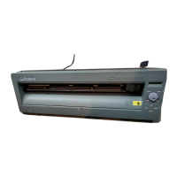
Details about the covers of the PC-60 unit.

1-2 Frame (1)

Main frame assembly (part 1) and its components.

1-3 Frame (2)

Main frame assembly (part 2) and its components.

1-4 Chassis

Exploded view and parts list for the main chassis.

1-5 Thermal Carriage

Components and parts list for the thermal carriage.

1-6 Tool Carriage

Components and parts list for the tool carriage.

1-7 Stand

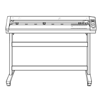
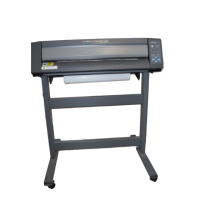
Parts list for the stand assembly.

1-8 Accessories

List of accessories for the PC-60 unit.

Electrical Section

2-1 Wiring Map

Electrical wiring diagram illustrating connections.

2-2 Main Board Assy

Details and circuit diagram of the main board.

2-3 Other Circuit Boards

Circuit diagrams for other related boards.

Replacement of Main Parts

3-1 Head Carriage Assembly_Quick Replacement

Procedure for quickly replacing the head carriage.

3-2 Head Carriage Assembly_Replacement

Detailed procedure for replacing the head carriage assembly.

3-3 Tool Carriage Assembly_Replacement

Procedure for replacing the tool carriage assembly.

3-5 Head Arm_Fixing

Instructions for fixing the head arm component.

3-7 Pinch Roller_Replacement

Procedure for replacing the pinch roller assembly.

3-8 Wire_Replacement

Procedure for replacing the wire component.

3-9 Motor_Fixing

Instructions for fixing the motor components.

Adjustment

4-1 Special Tool

List of special tools recommended for adjustments.

4-2 Service Mode

Instructions for entering and operating the service mode.

4-3 Factory Mode

Instructions for entering and operating the factory mode.

4-5 How to Upgrade Firmware

Steps to upgrade the unit's firmware via PC.

4-6 Tool Height Adjustment

Procedure for adjusting the tool height for print quality.

4-7 Tool Pressure Adjustment

Procedure for adjusting the tool pressure for cutting quality.

4-8 Head Voltage Adjustment

Procedure for adjusting the head voltage.

4-11 Head Position Adjustment 1

Procedure for head alignment (1st adjustment).

4-12 Head Position Adjustment 2

Procedure for head alignment (2nd adjustment).

4-13 Print;Cut Offset Adjustment

Procedure for adjusting print and cut alignment.

4-14 Cartridge Position Adjustment

Procedure for aligning cartridge position.

4-16 Grit Compensation

Procedure for adjusting media-feeding rate accuracy.

Supplemental Information

5-1 Operational Sequence

Flowchart detailing the unit's operational sequence.

5-2 Sensor Map

Diagram illustrating sensor locations and their functions.

Troubleshooting

6-1 Printing

Troubleshooting guide for printing related issues.

6-2 Cutting

Troubleshooting guide for cutting related issues.

6-3 Others

Troubleshooting for miscellaneous problems.

Supplement

7-1 Maintenance Check List

Checklist for performing regular maintenance.

7-2 Users DIP SW Setting

Explanation of user-configurable DIP switch settings.

7-3 Line Spacing Adjustment Mode

Procedure for adjusting the line spacing for users.

7-4 Specifications

Detailed technical specifications of the PC-60 unit.

Roland Color Camm Pro PC-60 Specifications

Operating Environment IconOperating Environment
operating temperature15—30ºC
operating humidity35—70% (non-condensing)
acoustic noise level (printing/cutting mode)less than 60 dB (A)
acoustic noise level (standby mode)less than 40 dB (A)
Power IconPower
power consumption at 100 V0.9 A
power consumption at 117 V0.8 A
power consumption at 220-240 V0.45 A
Performance IconPerformance
acceptable media width50 mm—610 mm
maximum work area571.6 mm x 24998 mm
acceptable media thickness0.23 mm—0.06 mm
cutter force30 gf—200 gf
cutting speed10 mm/sec.—200 mm/sec.
printing speedMax. 130 mm/sec.
cutting resolution0.025 mm/step
printing resolution600 dpi
cutting accuracyLess than +/-0.3 % of distance traveled or +/-0.3 mm
registration between printing/cuttingLess than +/-0.3 mm
System Memory IconSystem Memory
memory2 Mb
Ports & Interfaces IconPorts & Interfaces
interface typeParallel (Centronics), Serial (RS-232C, RS-422)
transmission speed (RS-232C)9600, 19200
transmission speed (RS-422)115.2 Kbps, 57.6 Kbps
Weight and Dimensions IconWeight and Dimensions
main unit dimensions (width x depth x height)1016 mm x 326 mm x 266 mm
main unit dimensions with open cover (width x depth x height)1016 mm x 326 mm x 355 mm
dimensions with stand (width x depth x height)1016 mm x 326 mm x 1125 mm
dimensions with stand and open cover (width x depth x height)1016 mm x 326 mm x 1214 mm
main unit weight26 kg
weight with stand45 kg

Related product manuals