19
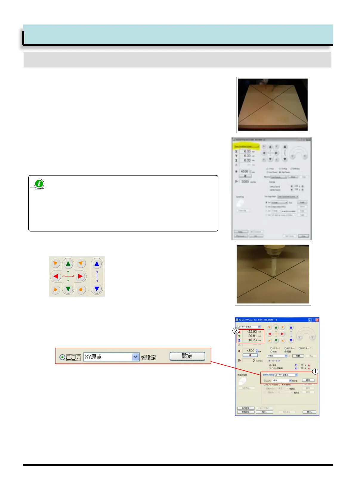
Setting the X- and Y- axis Origin Point
Draw diagonal lines from the corners of the
base material. This will give you the centre of
the material.
Start jklmnl
Change coordinate select (option [Ko in the diagram) to [User
Coordinate System]
pqser Coordinater
This allows the user to set the origin in any position.
p5achine Coordinater
These are the coordinates of the machine and the origin is set
at the initialisation point (after machine registers limit switches.
You cannot change this origin.
Set XY origin from VPanel.
Ksrom origin setting select [Set X origin here] then click
[Apply] button
1
2
3
Use cursor keys to move the tool tip to the center of the base.
4
LJheck that each XY origin coordinate now reads [0.00]
Step 3. Setup Tasks. Cutting the
Base and workpiece
h8]+<=$$*#B1$E=1&%*B*#1>&*#$1&_156789:;
 Loading...