Part No. 4801-5329 Rev 3-09 SW 100 Sidewall Curtain System Page 16
Figure 16 – Left Limit Switch Roller
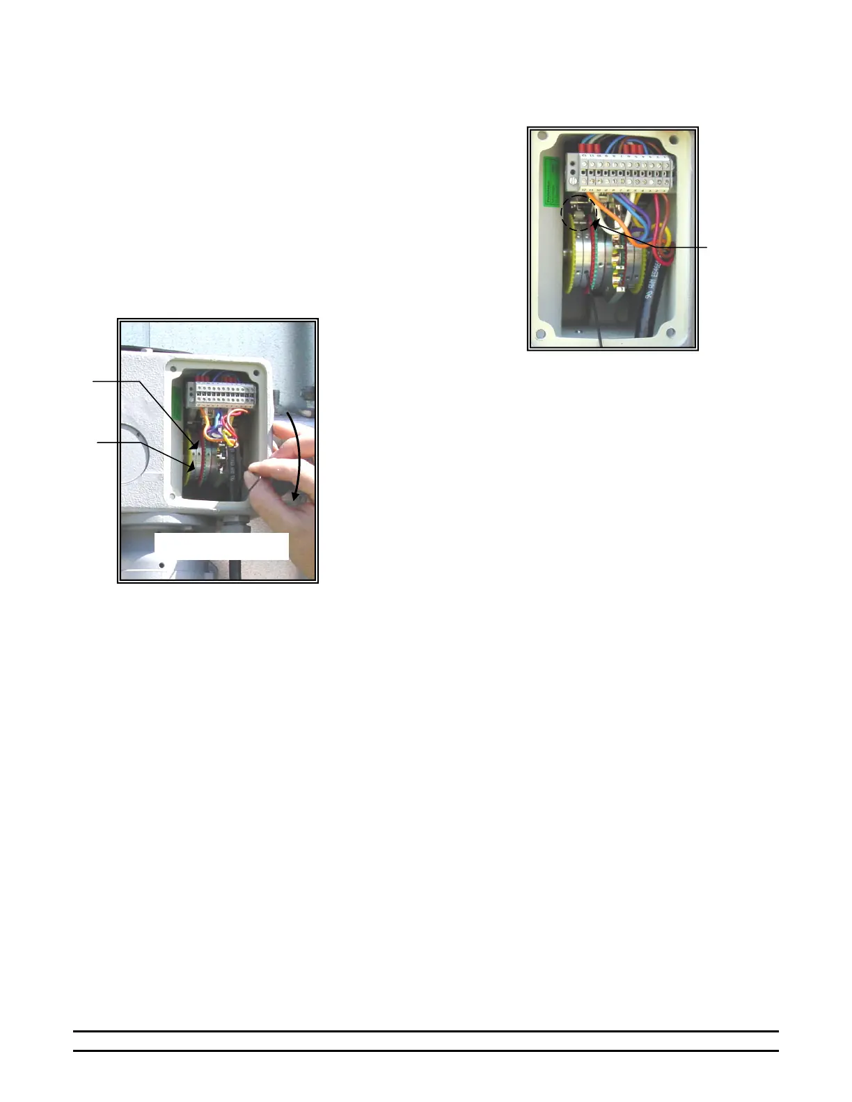
Limit
Switch
Roller
Setting
Rings
Hex
djusting
Screws
Figure 17 – Manually Open Curtain
4. With the curtain at the bottom limit, turn the Left Limit Switch’s 3
Setting Rings until the Limit Switch Roller [22] snaps into place in the
Switch Groove [21]. See Figure 16.
5. When the three switch grooves [21] are in line, the three Adjusting
Screws in the adjusting rings [9, 11, 13] are also in one line. Tighten
the screws in the setting rings [9, 11, 13] using a 1.5 mm hex wrench.
Torque to 1.3 to 1.5 in.-lb.
6. Open the Curtain. See Figure 17.
7. Turn the 3 Setting Rings of the Right Limit Switch like in Step
4.
8. Tighten screws in setting rings [15, 17, 19] to 1.3 to 1.5 in.-lb.
9. Verify the operation of the Limit Switch Settings by operating
the curtain from the controller.
10. Replace the tools in the Vinyl Seal and replace the Limit Switch
Cover [6] and Seal [30].
11. Door Panel Adjustments
During normal operation, the tension pipes should run in close proximity of each other. The clearance between the
tension pipes should normally be between 1/4" to 1/2" (6.35 mm - 12.7 mm). There are two situations pertaining to
the tension pipes that may cause problems with door operation. If the tension pipes are too far apart, the tension
pipes will not repel each other. This causes poor contact between the hook & loop. On the other hand, if the tension
pipes are riding one another (i.e. touching one another), the door panel material does not flow evenly, thus leaving
wrinkles in the panel instead of a stretched, smooth & even appearance.
Adjustment Procedures
The clearance between the tension pipes can be adjusted by raising or lowering the door panels. Each door has three
panels: (1) The inside panel (panel facing the inside of building) is attached to the back plate. (2) The center panel
is attached to the roller. (3) The outside panel (facing the outside of building) is attached to the front bar.
Adjustments are made to the inside panel and/or the outside panel. See Figure 18.
NOTE: The door must be in the closed position for panel adjustments. Ensure the panels are not damaged while
removing or reinstalling the nuts and screws.
Curtain Opens
 Loading...