Reference Manual
00809-0100-4809, Rev DA
Appendix A: Specifications and Reference Data
September 2015
115
Specifications and Reference Data
Coplanar MultiVariable sensor module
(3051SF_1, 2, 5, or 6)
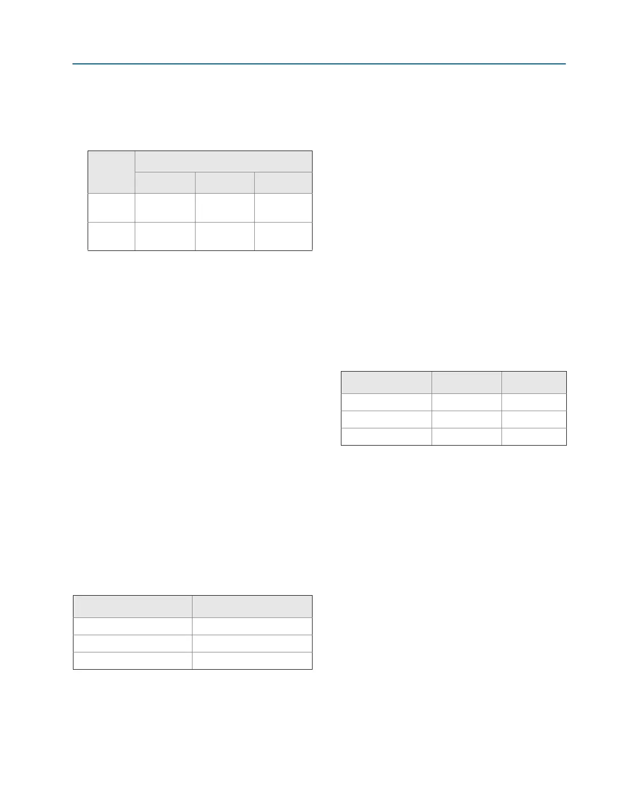
Operates within specifications between static line
pressures of 0.5 psia (0,03 bar) and the values in the table
below:
Burst pressure limits
Coplanar sensor module
10000 psig (689,5 bar)
Temperature limits
Ambient
Storage
Process temperature limits
For 3051SFA Temperature Limits, see page 161.
Humidity limits
0–100% relative humidity
When power is applied to the transmitter during startup,
performance will be within specifications per the time period
described in Table 5.
Volumetric displacement
Less than 0.005 in
3
(0,08 cm
3
)
Failure mode alarm
HART 4-20 mA (output option code A)
If self-diagnostics detect a gross transmitter failure, the
analog signal will be driven offscale to alert the user.
Rosemount standard (default), NAMUR, and custom
alarm levels are available (see Alarm configuration
below).
High or low alarm signal is software-selectable or
hardware-selectable via the optional switch (option D1).
Alarm configuration
Static
pressure
Differential pressure
Range 1 Range 2 Range 3
Range 3
GP/AP
800 psi
(55,15 bar)
800 psi
(55,15 bar)
800 psi
(55,15 bar)
Range 4
GP/AP
2000 psi
(137,90 bar)
3626 psi
(250,00 bar)
3626 psi
(250,00 bar)
-40 to 185 °F (-40 to 85 °C)
With LCD display
(1)
: -40 to 175 °F (-40 to 80 °C)
With option code P0: -20 to 185 °F (-29 to 85 °C)
1. LCD display may not be readable and LCD updates will be slower
at temperatures below -4 °F (-20 °C).
-50 to 185 °F (-46 to 85 °C)
With LCD display: -40 to 185 °F (-40 to 85 °C)
With Wireless Output: -40 to 185 °F (-40 to 85 °C)
Table 5. Turn-On Time
(1)
1. Does not apply to wireless option code X.
Transmitter
Turn-on time (typical)
3051S, 3051SF_D 2 seconds
Diagnostics 5 seconds
3051SMV, 3051SF_1-7 5 seconds
Damping
(1)
Analog output response time to a step change is
user-selectable from 0 to 60 seconds for one time constant.
For 3051SF_1-7, each variable can be individually adjusted.
Software damping is in addition to sensor module response
time.
1. Does not apply to wireless option code X.
High alarm Low alarm
Default 21.75 mA 3.75 mA
NAMUR compliant
(1)
1. Analog output levels are compliant with NAMUR
recommendation NE 43, see option codes C4 or C5.
22.5 mA 3.6 mA
Custom levels
(2)
2. Low alarm must be 0.1 mA less than low saturation and high
alarm must be 0.1 mA greater than high saturation.
20.2 - 23.0 mA 3.4 - 3.8 mA
Safety-certified transmitter failure values
(1)
Safety accuracy: 2.0%
(2)
Safety response time: 1.5 seconds
1. Does not apply to wireless option code X.
2. A 2% variation of the transmitter mA output is allowed before a safety
trip. Trip values in the DCS or safety logic solver should be derated by
2%.