XPression Prime Maintenance Guide (v01) Appendix A: Pinouts • A–1
Appendix A: Pinouts
This appendix provides information on the RS232 port pinouts.
RS232
XPression offers two GPI options:
• GPI 1: Data Set Ready pin 6 and pin 7
• GPI 2: Clear to Send pin 8 and pin 7
The RS232 port can also be used for CII using the XPression CII Gateway option.
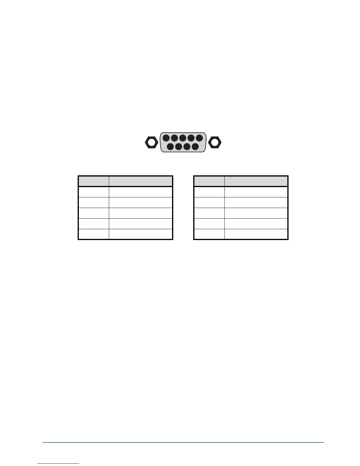
Figure A.1 RS232 — Male
When creating an RS232 GPI trigger, create a device that short-circuits either pin 8-7 or 6-7 on the nine pin
female connector. No additional power can be added to the circuit or it will damage the RS232 port.
Table A.1 RS232 Pinouts
Pin # Signal Pin Signal
1 Data Carrier Detect
6 Data Set Ready
2 Received Data
7 Request to Send
3 Transmitted Data
8 Clear to Send
4 Data Terminal Ready
9 Ring Indicator
5 Signal Ground
54321
9876