Wiring Instructions
AYC-x6355 Installation and User Manual 15
4. Wiring Instructions
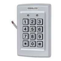
The units are supplied with a 10-conductor 18” (46 cm) pigtail or
with 10 terminal blocks.
To connect a pigtail reader to the controller:
1. Prepare the reader cable by cutting its jacket back 3.2 cm (1¼”)
and strip the insulation from the wires 1.3 cm (½").
2. Prepare the controller cable by cutting its jacket back 3.2 cm
(1¼") and strip the insulation from the wires 1.3 cm (½").
3. Splice the reader’s pigtail wires to the corresponding controller
wires (as indicated in Table 1) and cover each joint with insulating
tape.
Table 1: Wiring
Terminals
Wire Color Output
1 Red Power
2 Black Ground
3 Green Data 0 / Data
4 White Data 1 / Clock
5 Blue OSDP / RS-485-A2
6 Gray OSDP / RS-485-B2
7 Orange LED Control 1
8 Brown LED Control 2
9 Yellow Auxiliary Input
10 Purple Tamper Output
4. If the tamper output is being utilized, connect the purple wire to
the correct input on the controller.
The LED control may be configured by the factory to function
either as a LED control or as buzzer control. Currently, Auxiliary
Input is used as buzzer control and LED Control 1 is used as the
green LED control.
5. Trim and cover all unused conductors.
 Loading...
