3
2. Introduction
2.1 Caution
This manual has been written for the workshop
personnel assigned to using the lift (operator) and
for the engineer assigned to routine maintenance
(maintenance engineer). Therefore, before doing
anything with the lift and/or its packing, it is
necessary to read the entire manual carefully, as it
contains important information for:
•
THE SAFETY OF THE PERSONS assigned to its use
and routine maintenance.
•
THE SAFETY OF THE LIFT.
•
THE SAFETY OF THE LIFTED VEHICLES.
2.2 Conservation of the manual
The manual is an integral part of the lift and
must always accompany it, also in the case of sale.
It must always be kept close to the lift, in an easily
accessible place.
The operator and the maintenance engineer
must be able to find it and refer to it rapidly at any
time.
IN PARTICULAR, IT IS RECOMMENDED TO
READ CHAPTER 5 CAREFULLY AND
REPEATEDLY AS IT CONTAINS IMPORTANT
INFORMATION AND NOTICES RELATIVE TO
SAFETY.
2.3 Laws
The lifts have been designed and manufactured
in conformity with the following:
•
EN 1493:2010 Vehicle Lift
•
EN 60204-1:2006/AC:2010 Safety of machinery –
Electrical equipment of machines - Part 1: General
requirements
•
EN ISO 12100:2010 Safety of machinery - General
principles for design - Risk assessment and risk
reduction
•
EN 61000-6-2:2005+AC:2005 Electromagnetic
compatibility (EMC) Part 6-2: Generic standards —
Immunity for industrial environments
•
EN 61000-6-4:2007/A1:2011 Electromagnetic
compatibility (EMC) — Part 6-4: Generic standards —
Emission standard for industrial environments
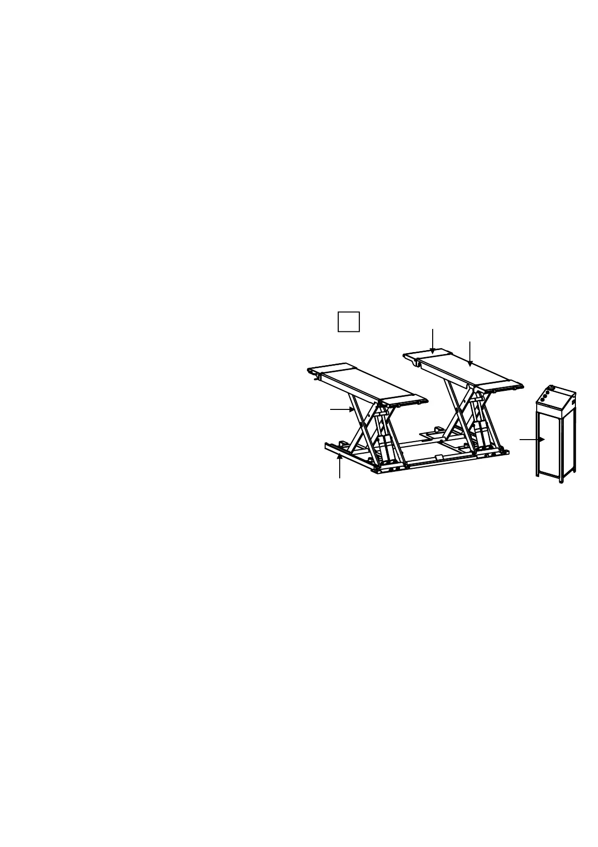
3. Description of the machine
The electro-hydraulic lift, is a fixed
installation; this means that it is anchored to the
ground and designed and built for lifting and
positioning automobiles at a certain height off the
ground.
The lift is driven by an electro-hydraulic operating
system.
The lift consists of the following main parts:
• fixed structure (base);
• mobile units (levers + lifting platforms);
• lift units (hydraulic cylinders and hydraulic unit);
• control box;
• safety devices.
Figure 4 illustrates the various parts making up the
lift.
3.1 Structure
It is composed of a base (1) made of welded
steel plates, two platforms (2), four ramps (3)
and two pairs of leg weldment (4).
The base has holes for fixing
to the ground by
means of optional anchor bolts. Inside the base
there are holes for the attachment of the lifting
legs. The platforms and legs are connected at the
ends by means of shafts and connected to the
base by means of special plastic supports. The
ramps are connected to the platform by means of
special shafts.
4
2
3
1
4
5

 Loading...