8
6. Installation
6.1 Warning
Unpack the goods and check for possible
damage before installing the car lift.
INSTALLATION REQUIREMENTS
The car lift must be installed according to the
specified safety distances from walls, columns,
other equipment, etc. The minimum distance from
walls must be 1000 mm at least, taking into
consideration the necessary space to work easily.
Further space for the control site and for possible
runways in case of emerg
ency is also necessary.
The room must be previously arranged for the
power supply.
The car lift can be placed on a horizontal
concrete floor with concrete quality C20/C25 and
a minimum thickness of 150 mm.
•
Place the car lift as required following the
instructions above indicated.
•
Connect hydraulic hoses A and B and the
drain hose E to the power pack in the control
box (page 16).
•
Use Dexron III ATF, or hydraulic fluid that
meets ISO32 specific cations into the tank.
•
Then carry out electrical connection (see.
Diagrams on pages 17 )
ATTENTION!
Skilled personnel only are allowed
to perform this operation.
ATTENTION!
The installation must comply with
the regulations in force and must be equipped with
relevant fuses (see electrical installation).
If you have ordered the anchor bolts. Keeping the
platform in the highest position, drill the
floor with
a helical bit having a diam. The size and depth of the
hole depends on the type of anchor bolt.
Clean the
holes,
insert the optional
anchor bolts and then
tighten with a torque wrench
of 40 Nm.
6.2 Attention
In case of using the platform in a definite place
of the workshop, it can be chosen to fixed to the
floor with optional anchor bolts or not fixed,
according to instructions contained in this manual.
(figure 11)
In case of moving the scissor lift to different
places by optional
mobile kit, the lift can be used
according to the following restrictions:
•
Place it on horizontal floor having proper
resistance.
•
Drive the vehicle on the cylinder opposite side
(see figure 12)
11
12
13
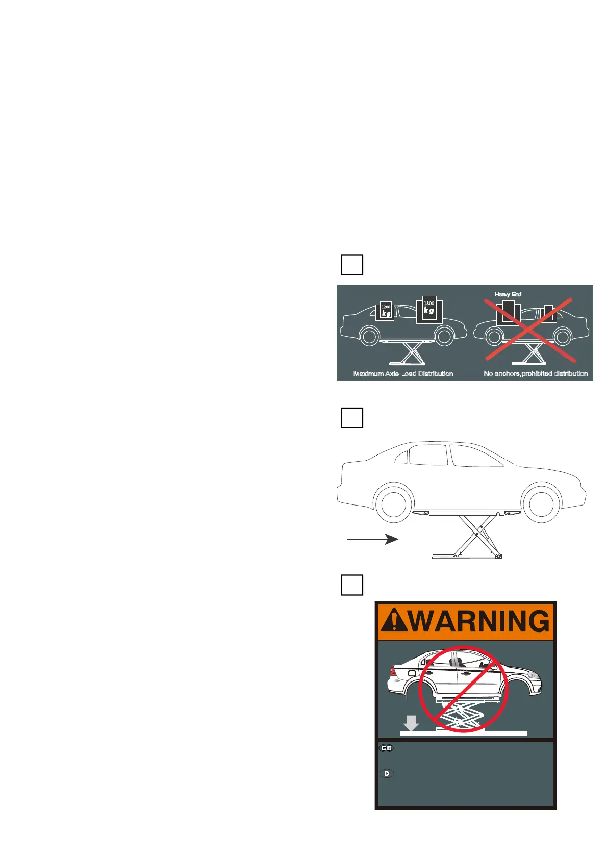
Maximum Axle Load Distribution
Heavy End
No anchors,prohibited distribution
Light End
1200
1800
BQ-122
Do Not lower lift to fully closed
when vehicle wheels are removed.
Die Hebebühne nicht zu weit
absenken,wenn die Räder
demontiert sind.

 Loading...