EasyManuals Logo

Rotax 912-UL User Manual

Rotax 912-UL
64 pages
To Next Page IconTo Next Page
To Previous Page IconTo Previous Page
Page #28 background imageLoading...
Page #28 background image
d03933
page 9 - 4
Jan. 01/2007
Effectivity: 912 Serie
OM Edition 1 / Rev. 0
BRP-Rotax
9.4) Electric system
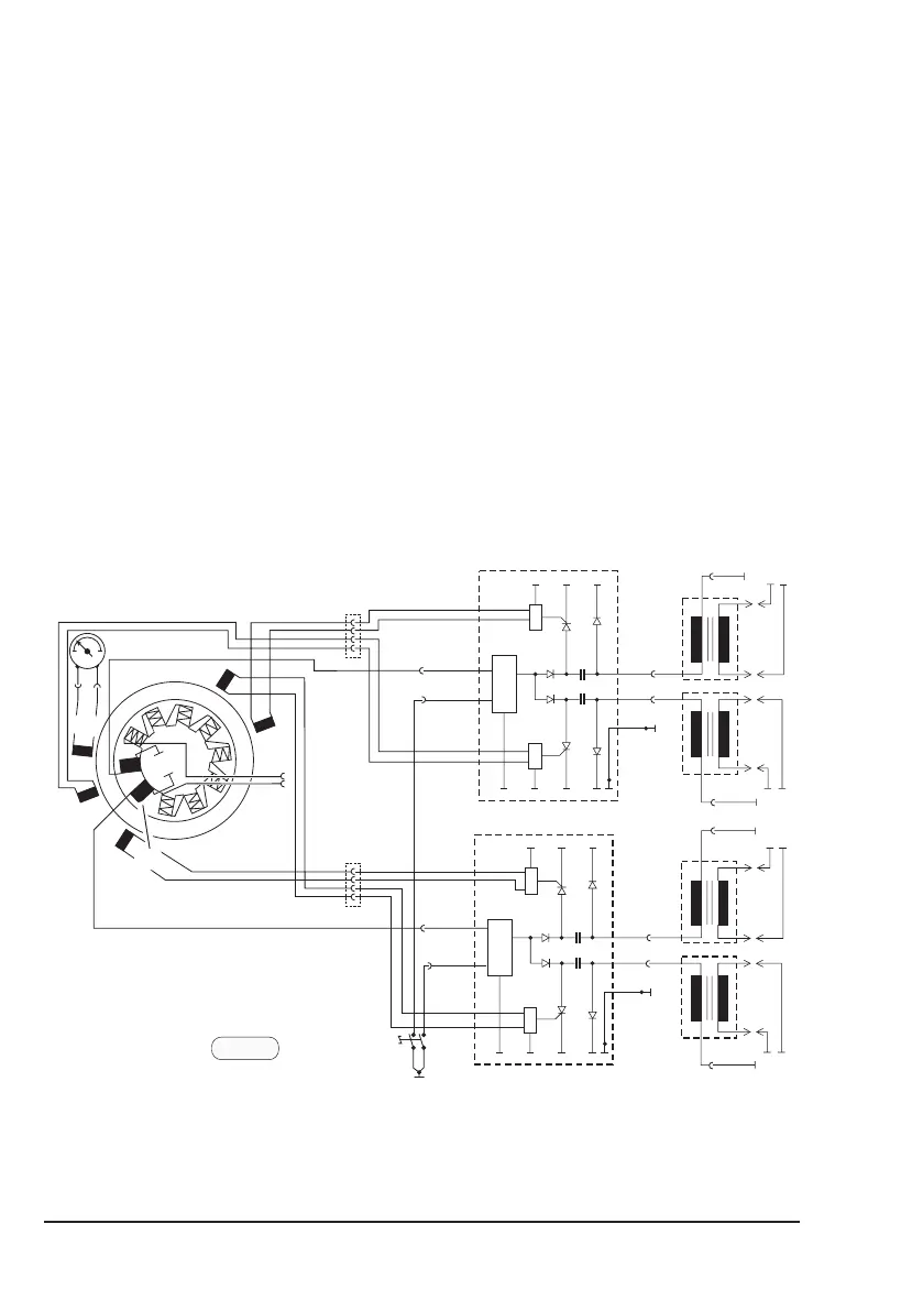
See fig. 7.
The ROTAX 912 engine is equipped with a dual ignition unit of a breakerless,
capacitor discharge design, with an integrated generator.
The ignition unit is completely free of maintenance and needs no external
power supply.
Two independent charging coils (1) located on the generator stator supply one
ignition circuit each. The energy is stored in capacitors of the electronic
modules (2). At the moment of ignition 2 each of the 4 external trigger coils (3)
actuate the discharge of the capacitors via the primary circuit of the dual
ignition coils (4).
Firing order: 1-4-2-3.
NOTE: The 5
th
trigger coil (5) is planned for rev. counter signal.
B1/2
B3/4
A1/2
A3/4
fig. 7
00425
Ignition circuit A
Ignition circuit B
4
2
4
3
3
5
1

Table of Contents

Other manuals for Rotax 912-UL

Questions and Answers:

Question and Answer IconNeed help?

Do you have a question about the Rotax 912-UL and is the answer not in the manual?

Rotax 912-UL Specifications

General IconGeneral
Displacement1211 cc
Bore x Stroke79.5 mm x 61 mm
Compression Ratio9.0:1
TBO (Time Between Overhaul)2000 hours
Engine Type4-cylinder, 4-stroke
Power Output80 hp
Cooling SystemLiquid/air-cooled
Fuel TypeAvgas 100LL or unleaded automotive gasoline
Oil Capacity3 liters
Fuel System2 carburetors
Oil SystemDry sump forced lubrication with separate oil tank
Reduction Gear Ratio2.43:1
Max Continuous Power75 hp (56 kW)

Related product manuals