Page | 16 DRM-3000 Operating Manual
The DRM-3000 is capable of supplying autonomous 24VDC through the Auxiliary connector only
if connected directly to the AC Power and if the optional DC power board exists in the Instrument.
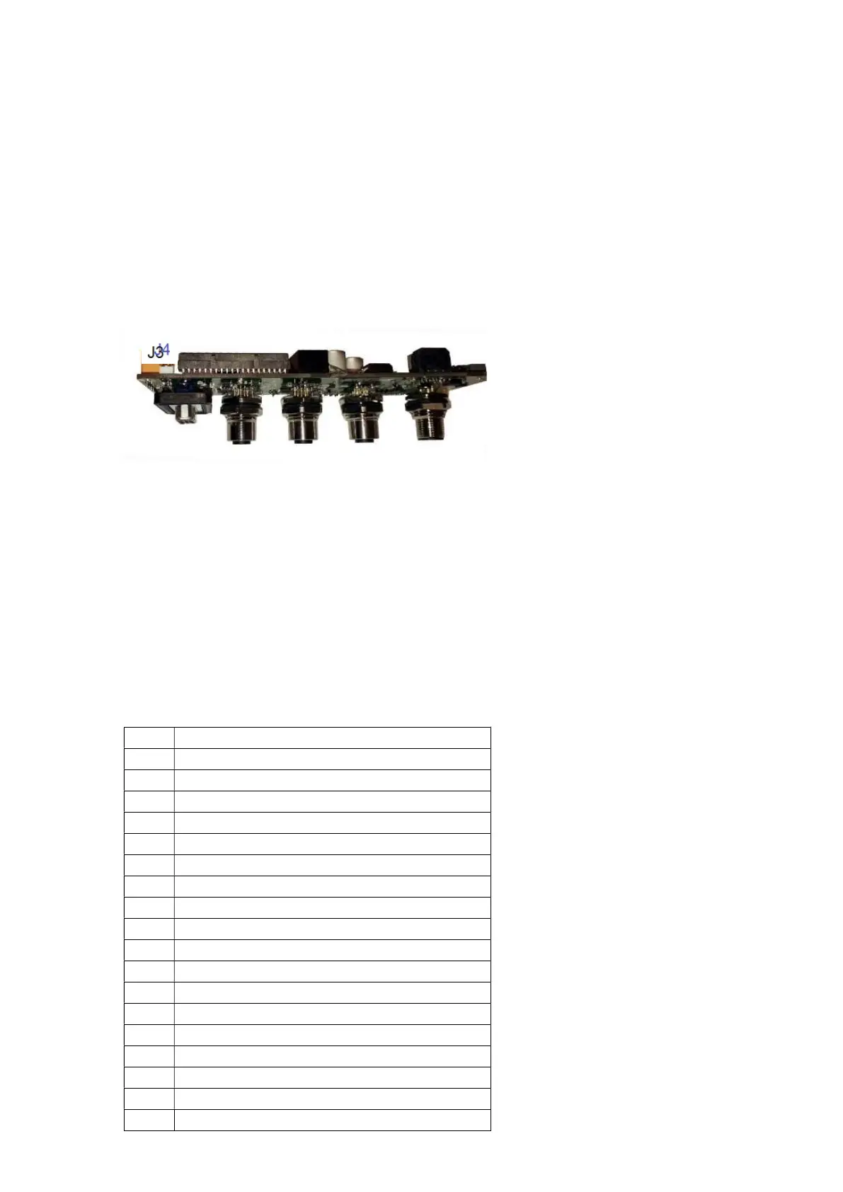
Additionally the routing of the 24V is defined by the placement of a jumper between pins J4
(behind J3).
If the Jumper is placed on J4 then 24 VDC will be supplied from Pin #5 continuously until an over
threshold condition occurs and then upon an over threshold condition 24 VDC will be supplied to
Pin #6 as long as the over threshold condition continues.
The DRM-3000 is also capable of supplying an external power source up to 10 µA 100 mV DC or
4A 250 VAC without being connected directly to the AC Power and without the DC power board.
3. RS-485 or RS-232 (two pins)
We have integrated a multiprotocol transceiver IC so that the user can select his preferable sort of
communication
RX – Pin #8
TX- Pin #9
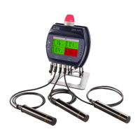
4. Output for external light tower
Pins 13 to 22 are dedicated to powering and controlling our signal light unit. The Light Tower
receives power from Pin #21 (OUT) and Pin #22 (GND).
5. Connector Schematics
1
2
3
4
5
6
8
9
10
OUT (Power To Flow Meter)
11 Flow Meter Input (4-20mA)
12
GND (Power To Flow Meter)
13 TWR CLEAR
14 TWR AMBER
15 TWR GREEN
16 TWR BLUE
17 TWR RED
18 TWR BZR1
21 TWR 24V OUT
22 TWR 24V GND