Page | 45 DRM-3000 Operating Manual
chart in the software (Src. – Source Number; Ref. Point – Defined Dose Rate; Distance –
Defined Distance from Source; Attenuator – user applied shielding factor for source – if
none is utilized enter 0). Below is an example of a Meter Calibration.
mR/h
mR/h
mR/h
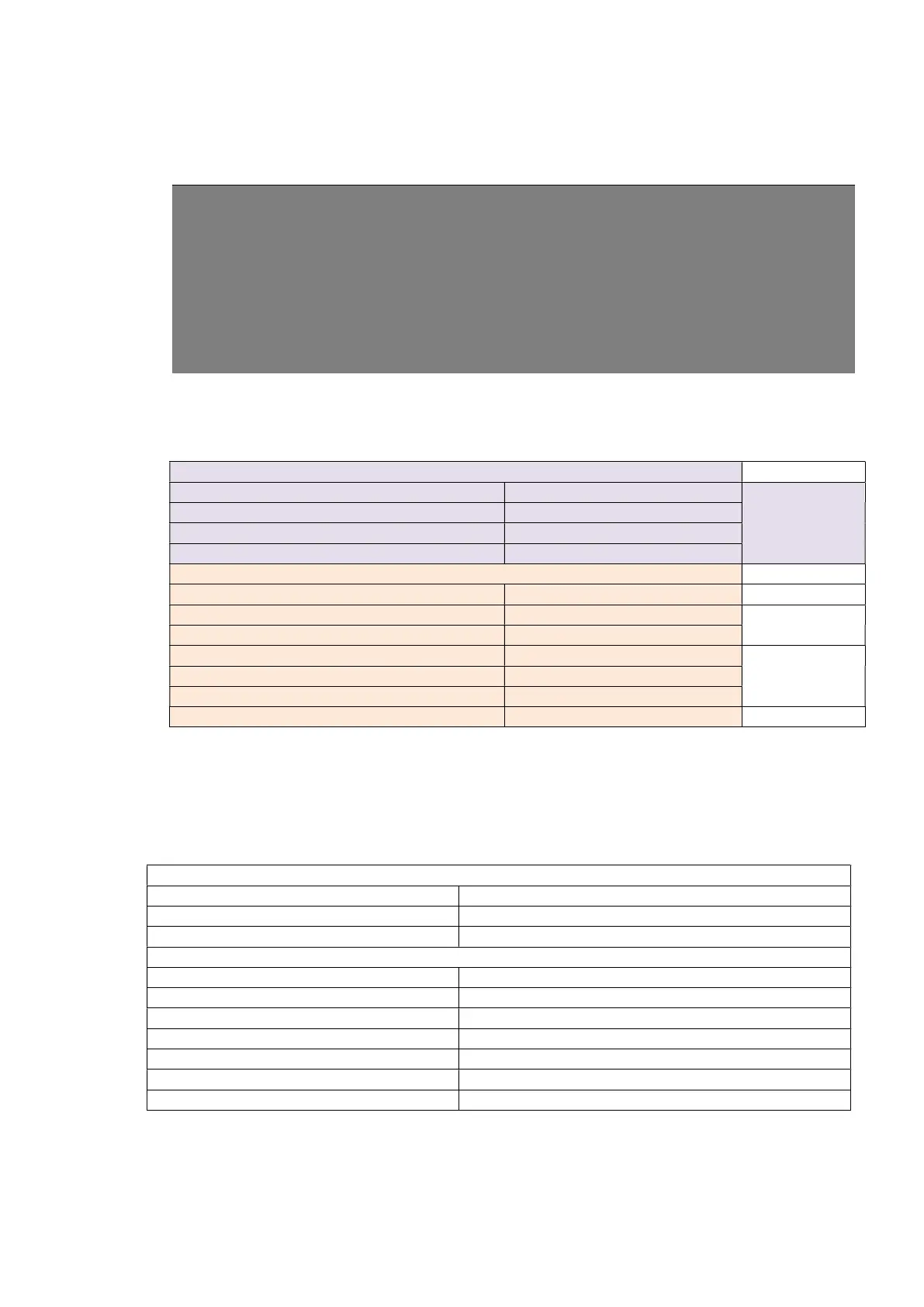
10.1.1 Recommended Calibration Points
ZP1201
0.1 to 1 mSv/h (10 to 100 mR/h) F1
4 to 15 mSv/h (400 to 1500 mR/h)
> 15 mSv/h (1500 mR/h) OFLO test
ZP1201
15 to 1,000 mSv/h (1.5 to 100 R/h) F3
ZP1301
3 to 10 Sv/h (300 to 1000 R/h) F5
4. Each calibration factor can be set within the range mentioned above (e.g. 0.1 mSv/h to 1
mSv/h) but we recommend that if possible each calibration factor be set in the middle of
each range. So for the range of 0.1 mSv/h to 1 mSv/h, we recommend that the detector is
placed in a dose rate field of 0.5 mSv/h.
7 mSv/h (700 mR/h) F2
CALIBRATION FACTORS
6.5 Sv/h (650 R/h) F5
5. The tight range for the F3 value is to provide good linearity for the High Range tube in the
switch – over range 1500 – 400 mR/h. Higher calibration points may be used if the
customer verifies acceptability of high range response in switch over range.
6. The above entered information may be saved as a template to be used for future