47User manual
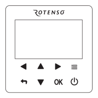
Wired control - ORIS
EN
No. Denition Description
31
Antepenultimate
alarm
-
32 Current protection P0-P3: check the detail in alarm table
33
Detail of P6 alarm in
function board
L-: no alarm;
L0: IPM or IGBT over current;
L1: lack of phase
L2: Compressor losing speed fault;
L3: DC voltage is too low to protect
L4: Fan motor over current protection
L5: Fan motor lack of phase;
L6: Fan motor zero speed fault
L7: PFC fault
L8: DC voltage is too high to protect
L9: Compressor zero speed fault
LA: PWM synchronization fault
Lb: MCE fault
Lc: Compressor over current protection
Ld: EEPROM data is wrong
LE: Compressor fail to start;
LF: fan motor losing speed fault
34
SV2 statue of water
loop
2-way valve which is used to change the cool/heat water between fan
coil and radiator (OFF-0; ON-1)
35
SV3 statue of water
loop
DHW 3-way valve
36
Main water loop EHs
statue
Standard equip with one EH, another two are eld supply (OFF-0; ON-1)
37 DHW EHs OFF-0; ON-1
38
External heat source
statue
OFF-0; ON-1
39 P_m External main water loop pump (OFF-0; ON-1)
40 P_p Second zone water loop pump (OFF-0; ON-1)
41 P_o First zone water loop pump (OFF-0; ON-1)
42
Anti-frozen heater
statue
OFF-0; ON-1
43 Chassis heater statue
OFF-0; ON-1
44 Crank heater statue OFF-0; ON-1
45
SV2 statue of
refrigerant syste
FCU water loop valve, to cut o water supply to radiator/space heater coil
in cool mode (OFF-0; ON-1)
 Loading...