4 x Operation
15
BA ROTEX A1 BG Inline - 10/2007
4Operation
4.1 Operating elements on the boiler control panel
4.1.1 Overview and brief description
All the important operating elements and electrical connections are integrated in the boiler switchboard. The electronics ensure
a smooth system operation.
Mains switch
Switching the gas condensing boiler on and off. When the heating system is on, the mains switch is illuminated green.
Collective fault signal
During normal operation, the collective fault signal is off. If it lights up this indicates a malfunction.
Pressure gauge
– Black pointer: Indication of the current water pressure in the heating system.
– Green range: Permitted water pressure range.
– Red pointer: Indication of the permitted minimum pressure.
The black pointer must be in the green range. If it is to the left of the red pointer, the water pressure must be raised by topping
up the system. If water needs to be filled frequently, please find out the reason for it and have the fault correct as soon as
possible.
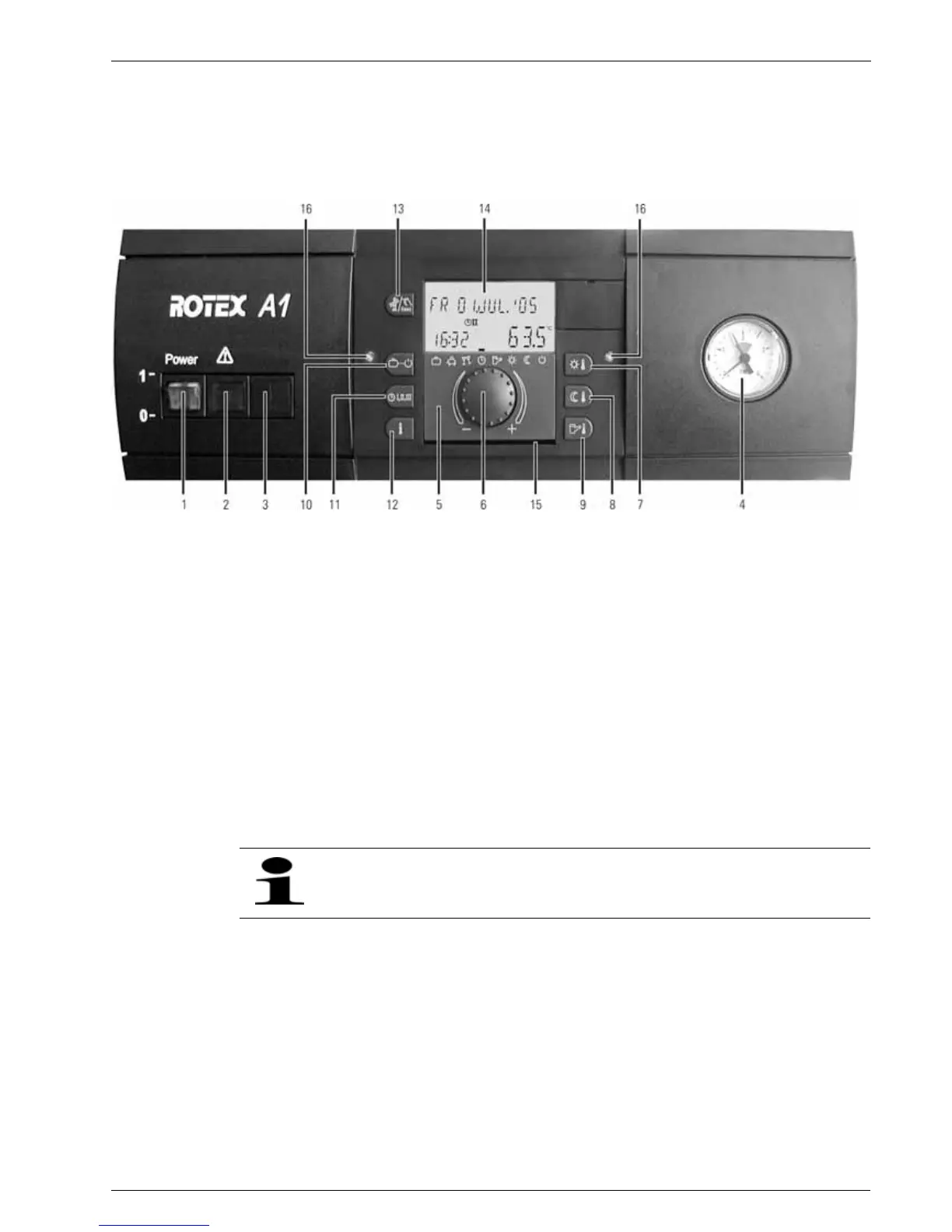
Fig. 4-1 Operating elements on the boiler control panel
1 Mains switch
2 Collective fault signal
3 Not assigned
4 Pressure gauge
5 Control: Central unit THETA 23R
6 Rotary switch for selecting and setting functions and
parameters
7 Selection of the target room day temperature
8 Selection of the reduced target room temperature
9 Selection of the target temperature for the hot water
storage tank
10 Selecting the mode
11 Setting Automatic timer program
12 System information
13 Emission measurement, manual operation, fault clearance
function
14 Display
15 Compartment for quick reference operating manual
16 Fixing bolts for the control
Malfunctioning is generally indicated by an error code on the display.
For troubleshooting instructions refer to Chapter 6.1 "Fault detection and troubleshooting".