7 x Technical data
34
BA ROTEX A1 BG Inline - 10/2007
Wiring diagram
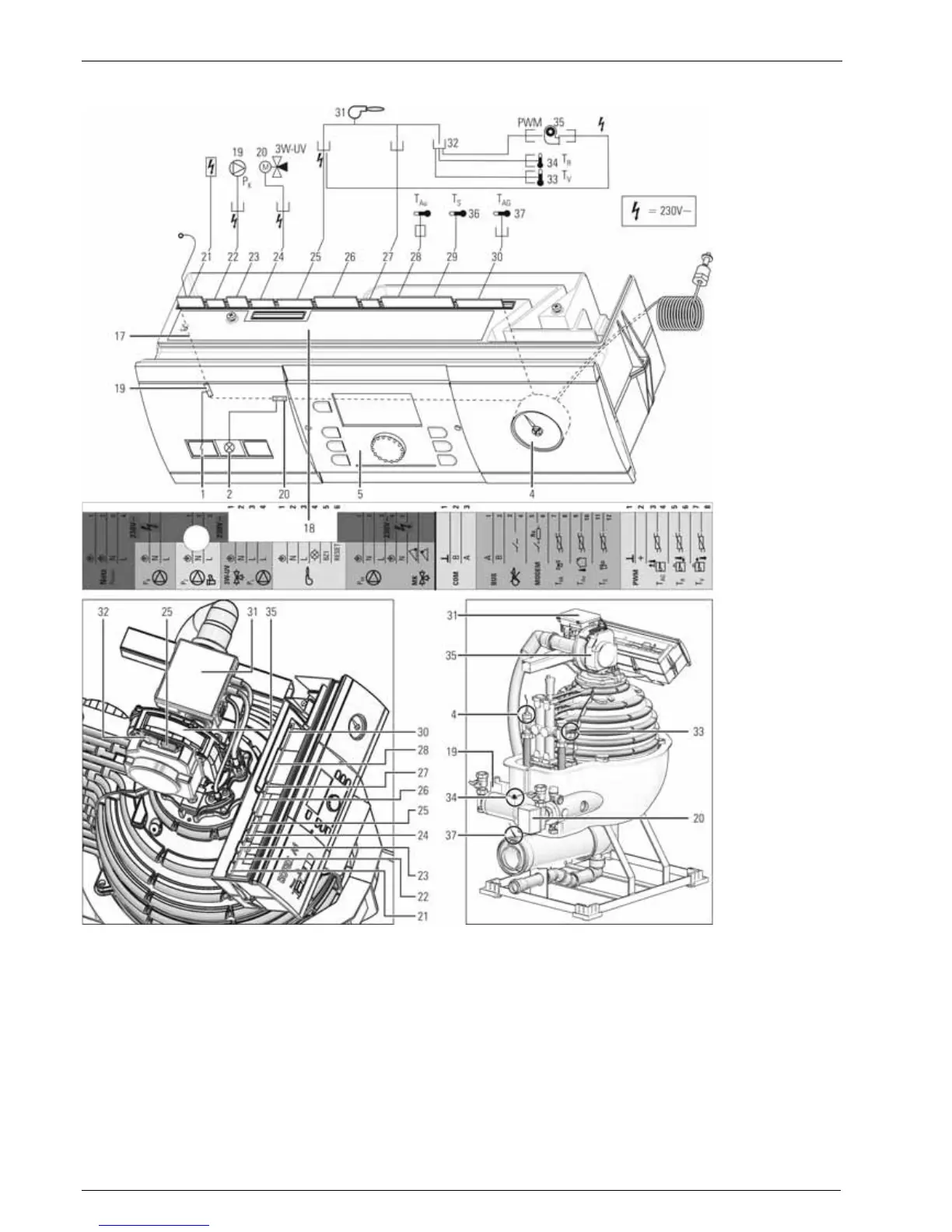
Fig. 7-7 Wiring diagram for the gas condensing boiler A1
1 Mains switch
2 Collective fault signal
4 Capillary tube pressure gauge
5 Control: Central unit THETA 23R
17 Control panel circuit board
18 Stickers for connection diagram
19 Circulation pump for heating
20 3-way switch valve
21 4-pin mains circuit board connector with clamped
mains cable and earthing connection
22 3-pin circuit board connector with pump cable
23 3-pin circuit board connector for connecting a
circulation pump
24 4-pin circuit board connector with valve cable
25 6-pin circuit board connector with clamped burner
cable
26 7-pin circuit board connector for clamping a mixer
motor or a mixer circulation pump
27 3-pin circuit board connector with communication
cable
28 External temperature sensor
29 12-pin circuit board connector for clamping
sensors, BUS and control lines
30 8-pin circuit board connector with flue gas sensor
cable
31 Modulating gas burner automatic firing unit
32 16-pin MOLEX connector with inflow, return flow
temperature sensor cable and fan control cable
33 Inflow temperature sensor
34 Return flow temperature sensor
35 Burner fan
36 Storage tank (hot water ) temperature sensor
37 Flue gas temperature sensor