4 x Operation
19
BA ROTEX A1 BG Inline - 10/2007
• Determine the hydraulic resistance in the heating network.
• Determine the necessary power stage of your heating pump on the basis of the Fig 4-5.
• Set the pump for the necessary output stage.
Example for determining the pump output stage
– Heat requirement: 16.6 kW, design temperatures: 75/60 °C, scatter: 15 K, requisite throughput quantity: 900l/m, hydraulic
resistance in the heating network: 250 mbar.
Î As designed, the pump stage 2 is sufficient. In the transition period, even pump stage 1 can suffice.
4.2.3 Tips about operating noises
In some cases, the resonance in the flue gas system can amplify the noise at the mouth of the flue gas duct. The noise level can
be effectively reduced by using a silencer ( 15 45 78).
Air suction noises are generated in ambient air-dependent operations. The noise level can be effectively reduced by using a
silencer ( 15 45 77).
4.3 Temporary shutdown
The design scatter describes the temperature difference between the heating inflow and heating return flow for
design conditions (as a rule -12 °C outside air temperature).
In practice, the hydraulic resistance in the heating network is often unknown. You can observe the inflow and
return flow temperature on the heat generator and determine if the pump still provides sufficient output at a
lower speed stage.
The difference between the inflow and return flow temperature must not increase beyond the design scatter and
each room must still heat up sufficiently.
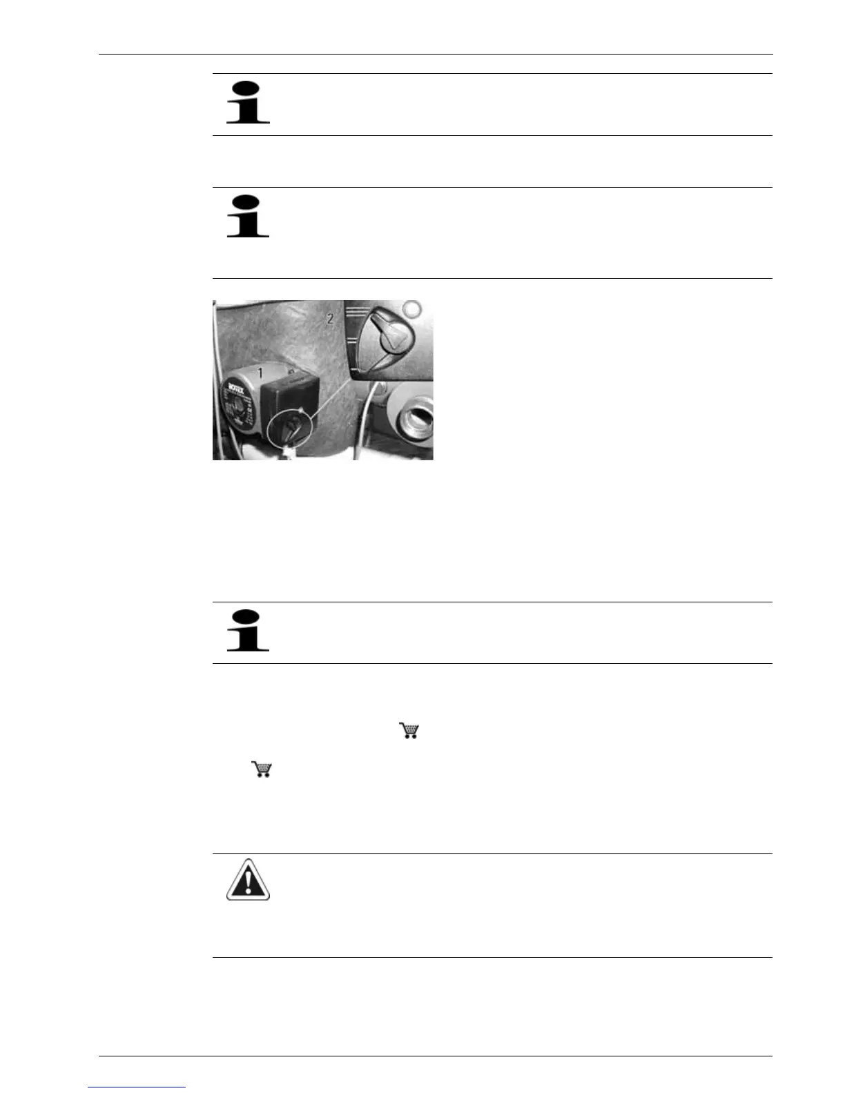
1 Heating pump
2 Setting lever of the pump output stage
Fig. 4-6 Setting pump output stage
The gas condensing boiler A1 BG 40i has a controlled heating pump, on which the heating expert makes the opti-
mum setting at the time of the initial start-up. The manual setting of the pump output stage is certainly also pos-
sible, but not necessary.
CAUTION!
A heating system which is shut down can freeze in the event of frost and may suffer damage.
• Drain the shut-down heating system if there is danger of frost.
• If the heating system is not drained, the gas and power supplies must be secured and the main switch must
remain switched on.