7 x Technical data
30
BA ROTEX A1 BG Inline - 10/2007
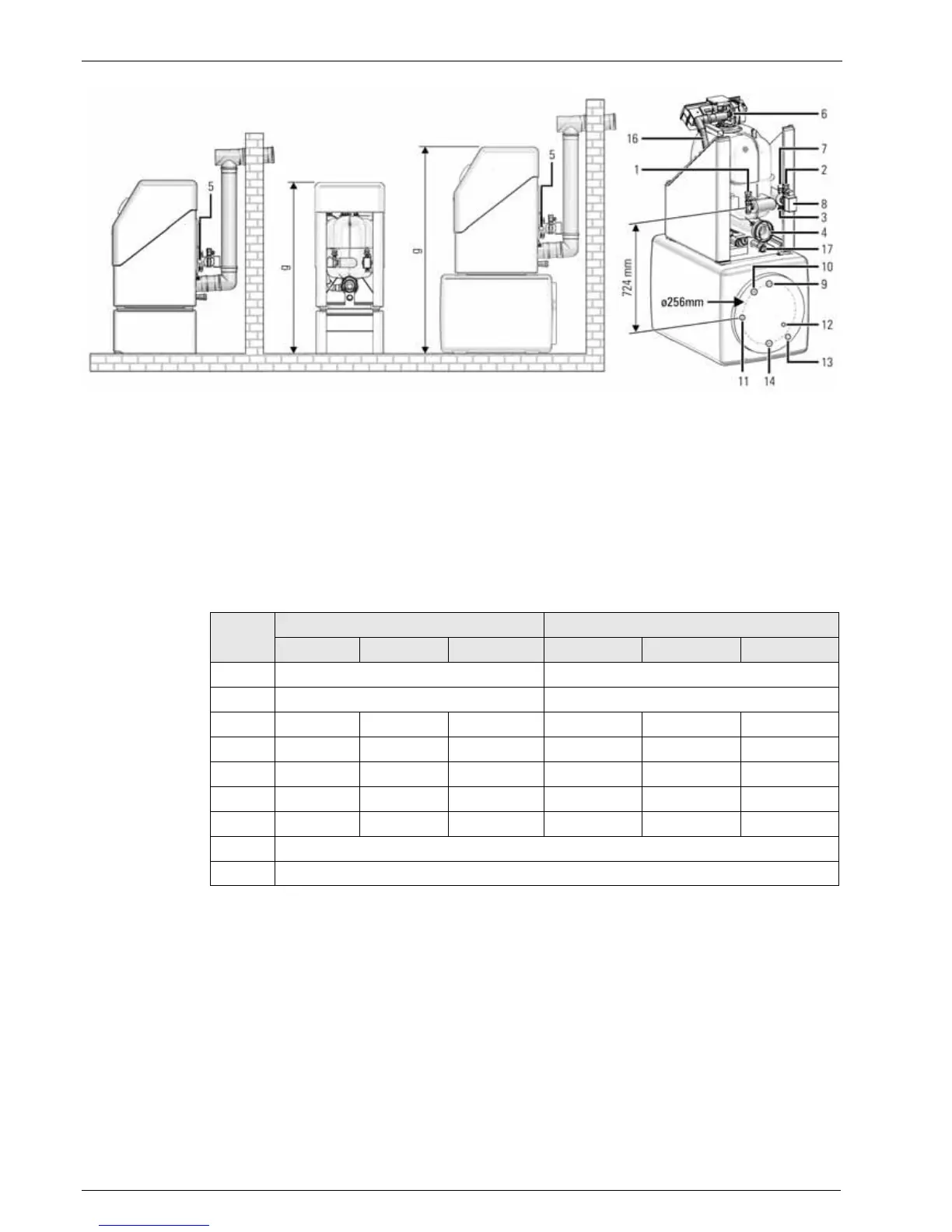
Tab. 7-1 Installation dimensions for gas condensing boilers A1 BG 25i / A1 BG 40i
Fig. 7-3 Dimensions and connection dimensions of the installation versions
1 Boiler return flow
2 Boiler inflow
3 KFE cock-Connection on the device
Filling line connection on the KFE
cock
4 Flue gas -/supply air connection
5 Connection expansion vessel
6 Burner
7 Safety valve
8 3-way-switch valve
G 1" FT (Box nut)
G 1¼" MT / G 1" FT
G ½" FT
G ½" MT
DN 80/125
G ½" FT
G ½" FT
G 1" MT
9 Hot water
10 Circulation
11 Heat exchanger return flow
12 Sensor immersion sleeve
13 Heat exchanger inflow
14 Cold water
15 Air/flue gas system (LAS) Connection piece
16 Supply air hose
17 Condensate discharge hose
G ¾" FT
G ¾" FT
G ¾" MT
G ¾" MT
G ¾" FT
DN 80/120
DN 50
DN 40
Dimension A1 BG 25i / mm A1 BG 40i / mm
on the floor on US 150 on underframe on the floor on US 150 on underframe
a
≥400 ≥400
b 720 720
c
≈90 ≈750 ≈470 ≈90 ≈750 ≈470
d 230
±
15
880
±
15
590
±
15
230
±
15
880
±
15
590
±
15
e 400
±
15
1040
±
15
790
±
15
460
±
15
1100
±
15
850
±
15
f ≥1340 ≥1890 ≥1650 ≥1590 ≥2140 ≥1890
g 1100 1730 1480 1340 1970 1720
h 625
i 300