7 Installation
Installer reference guide
36
RVLQ05+08CAV4 + RHYHBH05AA + RHYHBH/X08AA +
RHYKOMB33AA
ROTEX HPU hybrid
4P355635-1 – 2013.05
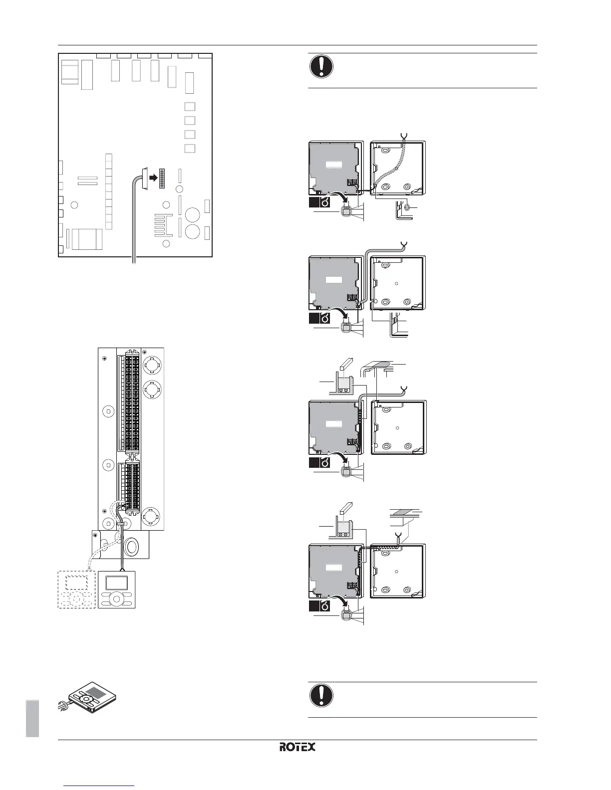
X39A
9 Close the switch box cover of the indoor unit.
10 Close the switch box cover of the gas boiler.
11 Close the gas boiler.
7.8.7 To connect the user interface
1 Connect the user interface cable to the indoor unit.
X2M
X1M
1
2
X5M
2 Fix the cable with cable ties to the cable tie mountings.
To fix the user interface to the wall in case of
installation as room thermostat
1 Insert a screwdriver into the slots underneath the user interface
and carefully separate the faceplate from the wallplate.
NOTICE
The PCB is mounted in the faceplate of the user interface.
Be careful NOT to damage it.
2 Fix the wallplate of the user interface to the wall.
3 Connect the wires to the user interface as shown below
From the rear
b
a
PCB
1x
From the left
a
PCB
b
1x
From the top
a
b
PCB
b
1x
From the top center
a
PCB
b
b
1x
a
Notch this part for the wiring to pass through with
nippers etc.
b
Secure the wiring to the front part of the casing
using the wiring retainer and clamp.
4 Reinstall the faceplate onto the wallplate.
NOTICE
Be careful NOT to pinch the wiring when attaching the
frontplate to the unit.
 Loading...


