14 Disposal
Installer reference guide
86
RVLQ05+08CAV4 + RHYHBH05AA + RHYHBH/X08AA +
RHYKOMB33AA
ROTEX HPU hybrid
4P355635-1 – 2013.05
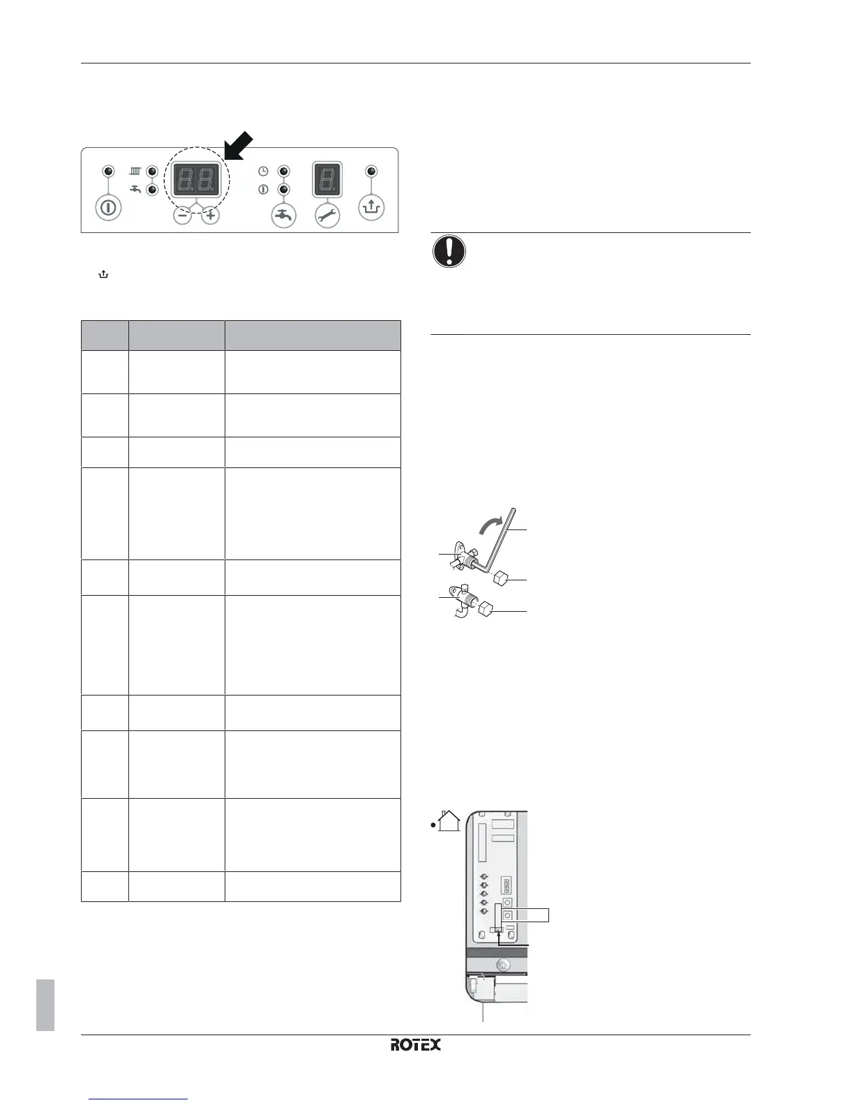
Error codes of the gas boiler
The controller on the gas boiler detects faults and indicates them on
the display by error codes.
If the LED is flashing, the controller has detected a problem. Once
the problem is rectified, the controller can be restarted by pressing
the button.
Following table shows a list of error codes and the possible
solutions.
Error
code
Cause Possible solution
10, 11,
12, 13,
14
Sensor fault S1 ▪ Check wiring
▪ Replace S1
20, 21,
22, 23,
24
Sensor fault S2 ▪ Check wiring
▪ Replace S2
0 Sensor fault after
self-check
Replace S1 and/or S2
1 Temperature too
high
▪ Air in installation
▪ Pump is NOT running
▪ Insufficient flow in installation
▪ Radiators are closed
▪ Pump setting is too low
2 S1 and S2
interchanged
▪ Check cable set
▪ Replace S1 and S2
4 No flame signal ▪ Gas tap is closed
▪ No or incorrect ignition gap
▪ Gas supply pressure is too low or
fails
▪ Gas valve or ignition unit is NOT
powered
5 Poor flame signal ▪ Condensate drain blocked
▪ Check adjustment of gas valve
6 Flame detection
fault
▪ Replace ignition cable and spark
plug cap
▪ Replace ignition unit
▪ Replace boiler controller
8 Incorrect fan speed ▪ Fan catching on casing
▪ Wiring between fan and casing
▪ Check wiring for poor wire contact
▪ Replace fan
29, 30 Gas valve relay
fault
Replace boiler controller
14 Disposal
14.1 To pump down
In order to protect the environment, be sure to pump down in
following cases:
▪ when relocating or disposing of the unit,
▪ after maintenance or service to the refrigerant side of the system.
NOTICE
During pump down operation, stop the compressor before
removing the refrigerant piping. If the compressor is still
running and the stop valve is open during pump down, air
will be sucked into the system. Compressor breakage and
other injury will be the result due to abnormal pressure in
the refrigerant cycle.
Pump down operation will extract all refrigerant from the system into
the outdoor unit.
1 Remove the valve lid from liquid stop valve and gas stop valve.
2 Carry out the forced cooling operation.
3 After 5 to 10 minutes (after only 1 or 2 minutes in case of very
low ambient temperatures (<−10°C)), close the liquid stop valve
with a hexagonal wrench.
4 Check with the manifold if the vacuum is reached.
5 After 2-3 minutes, close the gas stop valve and stop forced
cooling operation.
a
c
b
d
d
e
a
Gas stop valve
b
Closing direction
c
Hexagonal wrench
d
Valve lid
e
Liquid stop valve
14.2 To start and stop forced cooling
Confirm that dipswitch SW2 is in COOL mode.
1 Press the forced cooling operation switch SW1 to begin forced
cooling.
2 Press the forced cooling operation switch SW1 to stop forced
cooling.
SW1
H
E
A
T
C
O
O
L
SW2

 Loading...


