Sound System Setup GrandSTAR Internet Jukebox
3-6 22022603
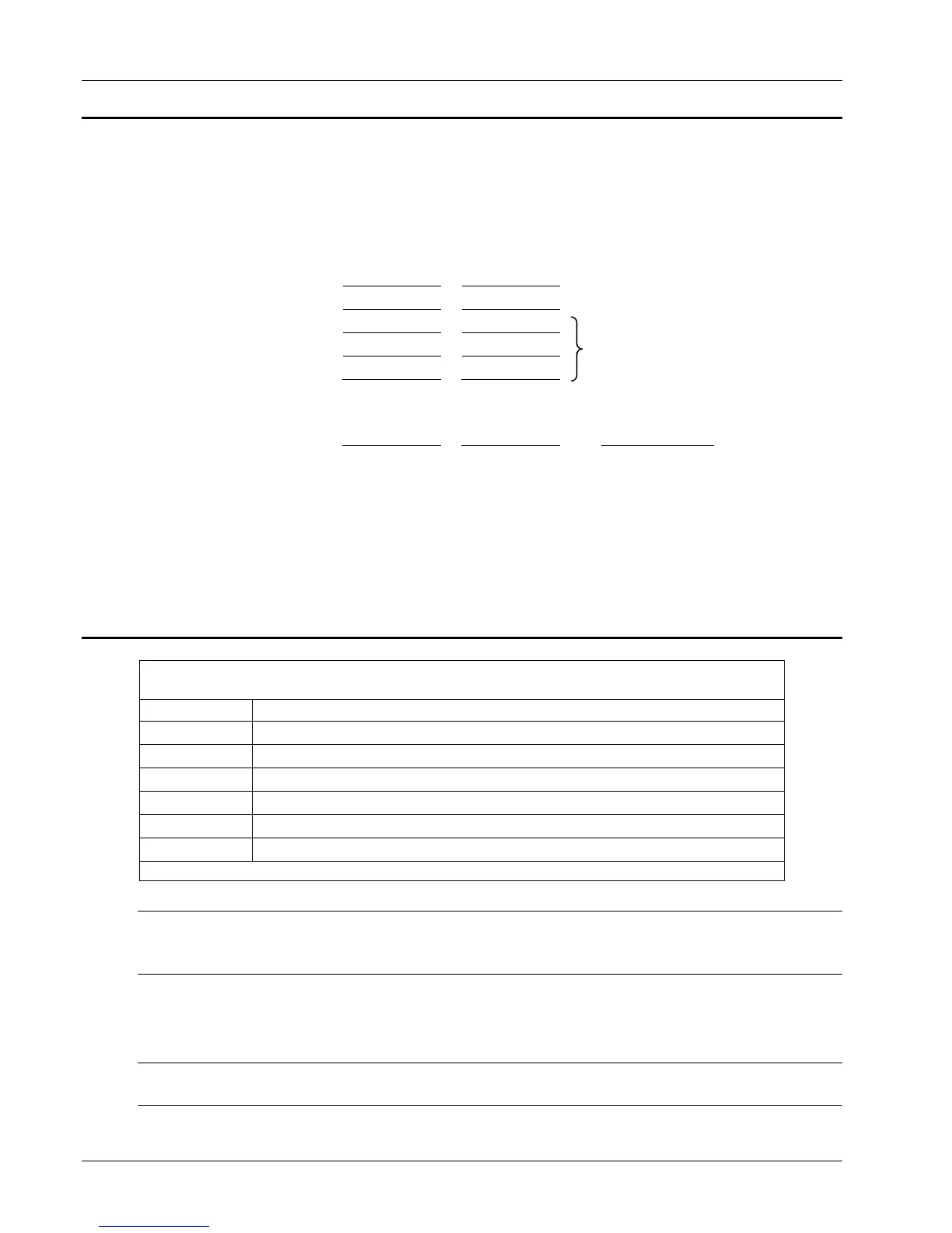
Table 3-4 - Extension Speaker Worksheet
Sheet 4
Combine power consumption of all speakers:
Channel 1 Channel 2
Connected E1 to E7
Tapped 4-ohm
Tapped 8-ohm
70-Volt A1, A2
Channel 1 Channel 2 Grand Total
Totals: + =
1. The Grand Total is the amount of power that the jukebox will need to supply to the
extension speakers. If the Channel 1 Total "or" the Channel 2 Total is more than 438
watts, you must reduce the power used by that channels extension speakers, then
recalculate that channels power consumed. The jukebox internal speakers consume
62 watts per channel (factory wiring). This leaves (500-62.5) 437.5 watts per channel
for extension speakers.
2. The jukebox wires to change are the Violet (Channel 1) and the Pink (Channel 2) on
the Output Transformer Assembly (See Table 3-5).
Use Table 3-5 as a guide to select the power used by the jukebox.
Table 3-5 -
Jukebox Speaker Power
Select the speaker taps for the internal jukebox speakers.
You may select more or less jukebox power to suit your jukebox volume.
Phono Power Phono Speaker Connections
.25
Violet connects to Channel 1 E2, Pink connects to Channel 2 E2.
1
Violet connects to Channel 1 E3, Pink connects to Channel 2 E3.
4
Violet connects to Channel 1 E4, Pink connects to Channel 2 E4.
16
Violet connects to Channel 1 E5, Pink connects to Channel 2 E5.
36
Violet connects to Channel 1 E6, Pink connects to Channel 2 E6.
62.5
Violet connects to Channel 1 E7, Pink connects to Channel 2 E7.
The Black or Black/White wires are on the Channel 1 and Channel 2 E1 terminals.
NOTE: In any speaker installation, the total RMS speaker load (the sum of all power to all
speakers) must not exceed 500 watts per channel. It is strongly recommended that
“Efficient” extension speakers be used.
3. When you have reached a satisfactory combination of speakers and speaker power
consumption, connect the E1 to E7 speakers and the 70V speakers A1 to A2. Then
use the “Connections” column as a guide to wire the tapped E1 through E6
speakers.
NOTE: The amplifier may be connected to a load of 500 watts per channel before distortion
will begin to increase beyond specification.
Sum of tapped, and
70 Volt A1, A2 must
not exceed 125 watts
per channel.



 To Next Page