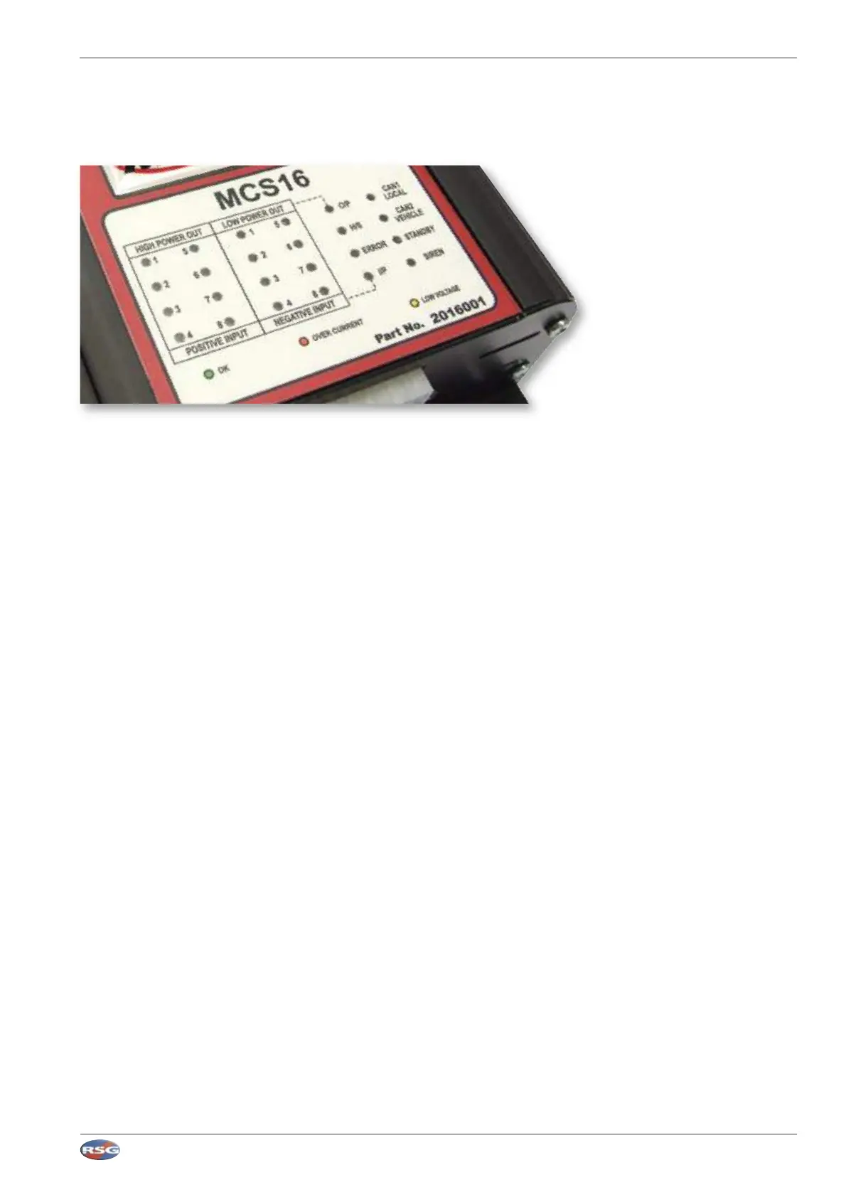
3.7 Diagnostics (Front label LED indicators)
The MCS-16 has 24 diagnostic LED's on the top side of the unit, which can be used to assist the installer in finding faults, etc.
• CAN1 and CAN2
a OFF : The respective CAN port is not being used
b RED : The respective CAN port has a fault condition
c GREEN : The respective CAN port is working correctly
• H/S (Handset)
a OFF : The RS485 port is not being used (has not been configured in software)
b RED : The RS485 port has not detected a remote handset
c GREEN : The RS485 has detected a working handset
• STANDBY
a SLOW PULSING GREEN : Unit has entered Standby Mode
b OFF : Standby feature is not enabled
c AMBER : If the Standby Mode is enabled the LED shows amber while the unit is timing down to Standby Mode
d RED : Unit will not enter Standby Mode until active outputs are de-activated
• SIREN
a OFF : Siren has not been configured in software
b SLOW PULSING GREEN : Siren is in low power standby mode (Not Enabled)
c FAST PULSING GREEN : Siren is internally powered and ready to operate
d GREEN : Siren Output is operating (speaker is sounding)
e RED : Over-Current Safety - Siren System Disabled (Reset Required)
f AMBER : Low Voltage Dropout (The siren is disabled because supply is too low)
RSG Engineering Limited Telephone : 01543 438800 Fax : 01543 438801 Email : sales@rsg-ontop.com Web : www.rsg-ontop.com
2:40
UNIVERSAL CONTROLLER LITE (MCS-16) USER GUIDE V1 3 : SYSTEM DESCRIPTION
3 : Sytem Description continued