• O/P and I/P. User Diagnostics.
Pressing the diagnostics button will scroll through several ‘pages’ of information that are reflected on the 2 groups of
LEDs 1 - 8 relating to inputs and outputs. The O/P and I/P LEDs are the key to which page is currently reflected on the LED's.
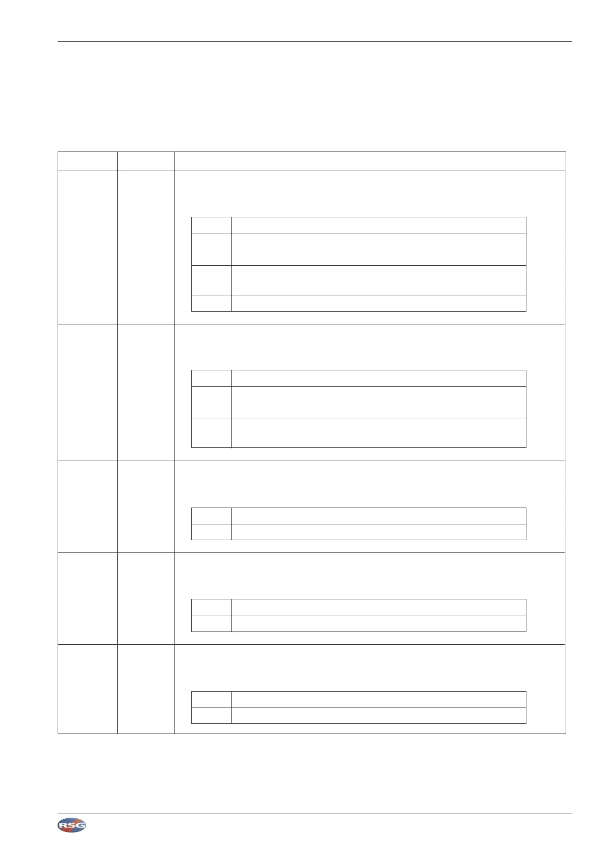
O/P I/P DISPLAY
OFF OFF High Power Outputs. LEDS 1 - 8 display the state of the outputs.
The following table defines the state of the output:
OFF The output is not enabled
GREEN The output is enabled (this does not show the flash pattern, only that
the output is active)
AMBER The output is enabled, but the supply voltage has dropped below the
set level (Voltage Dropout)
RED The output is disabled because of an excessive current fault
GREEN OFF Low Power Outputs. LEDS 1 - 8 display the state of the outputs.
The following table defines the state of the output:
OFF The output is not enabled
GREEN The output is enabled (This does not show the flash pattern,
only that the output is active)
AMBER The output is enabled, but the supply voltage has dropped
below the set level (Voltage Dropout)
RED OFF H/S - Handset Inputs (RS485 or PWM)
LEDS 1 - 16 display the state of the inputs on the 2 groups of 8.
RED The button is not pressed \ off
GREEN The button is pressed
OFF GREEN Positive Inputs (Inputs Connector)
LEDS 1 - 8 display the state of the inputs.
RED The input is low (0V)
GREEN The input is high (>4V)
OFF RED Negative Inputs (Inputs Connector)
LEDS 1 - 8 display the state of the inputs.
RED The input is low (0V)
GREEN The input is high (>4V)
RSG Engineering Limited Telephone : 01543 438800 Fax : 01543 438801 Email : sales@rsg-ontop.com Web : www.rsg-ontop.com
2:41
UNIVERSAL CONTROLLER LITE (MCS-16) USER GUIDE V1 3 : SYSTEM DESCRIPTION
3 : Sytem Description continued