ECT Series User Manual
2
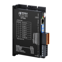
Incremental orthogonal encoder
24 V input for 4 common anodes
2 channels: alarm, lock, in place and general output
Dual RJ45, with communication LED indication
*Please do not exceed the scope of use specified above.
*Before enabling the motor, the user needs to set the operating current according to the motor
specifications, otherwise the current setting beyond the rated range may cause the motor to
burn.
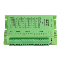
1.2 Power and motor
For ECT42、ECT60, the power supply is DC power supply, V+ is
connected to the positive pole of the power supply, and V- is
connected to the negative pole of the power supply. The
recommended power supply voltage is 24~80VDC..
For ECT86, the power supply is AC and DC compatible power supply.
AC and AC can input 24~100V DC power, and can also input 24~80V
AC power.
*The above power supply voltage is the limit value of the driver. Due to
the influence of the back electromotive force of the stepper motor, the
customer needs to reserve a certain voltage margin when using it.
Two phase stepper motor winding connection port, specific motor wire
connection please refer to the motor manufacturer instructions.
Encoder input interface, specific encoder connection please refer to
the motor manufacturer instructions.