ECT Series User Manual
3
1.3 Digital input and output ports
ECT series can no longer be used for other input port functions because IN1 and IN2 are
assigned to orthogonal encoder interfaces and will not work for IN1、IN2 function settings.
1.3.1 Digital input port
ECT series step driver has 4 channels digital input port ,2 channels digital output port. The
object dictionary 0x2007 is the function setting of the input port and 0x2008 is the polarity
setting of the input port.
Note: IN1+ / IN1-、IN2+ / IN2- is motor encoder input terminal, do not directly connect the input
signal higher than this voltage, otherwise the driver will be damaged!
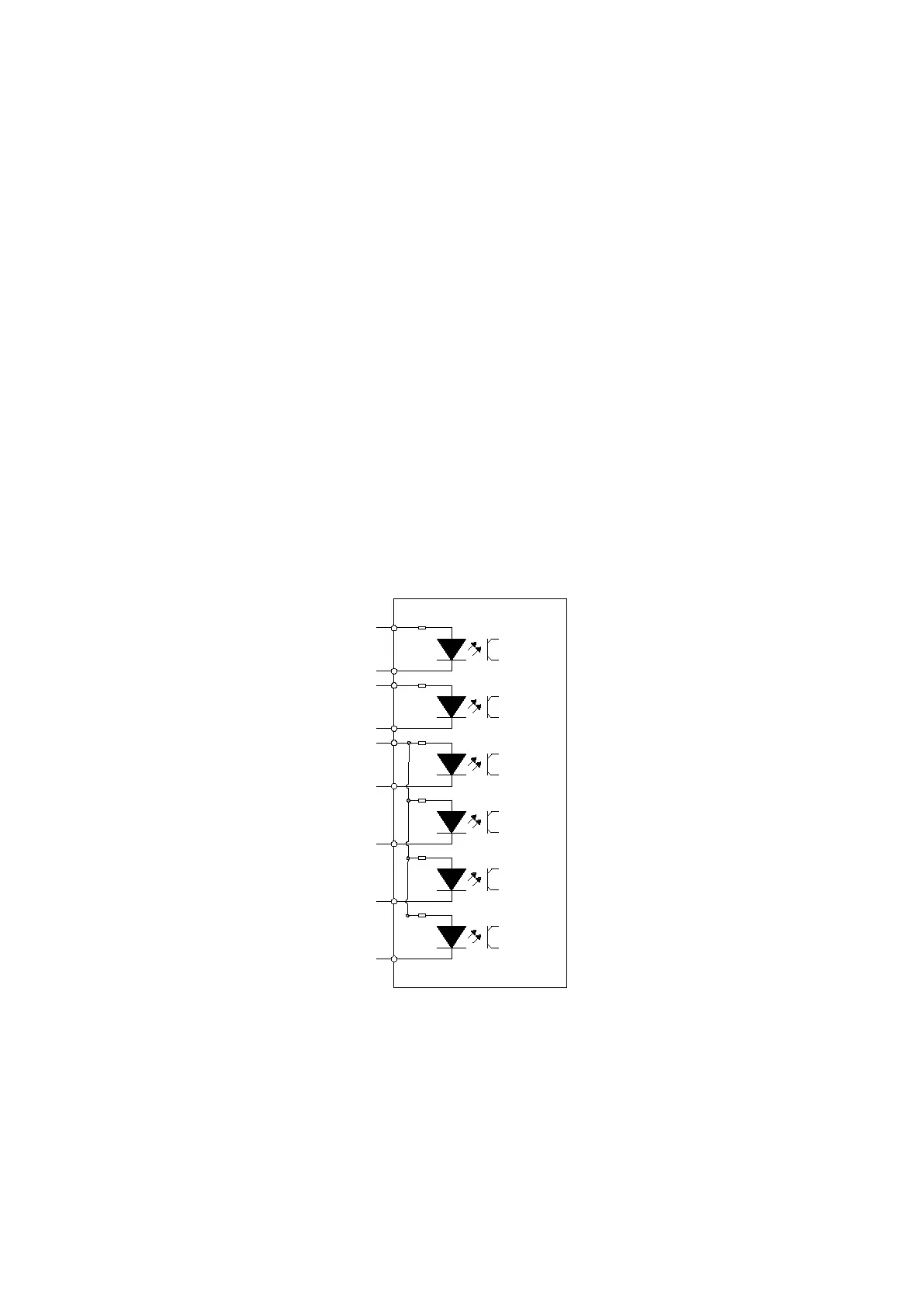
The schematic diagram of the input port is shown below, and the user can connect the system
according to the schematic diagram.
驱动器
+24V
IN1
IN2
IN3
IN4
IN5
IN6
驱动器
OUT1
OUT2
OUT3
OUT4
0V
NR60-6IN数字IO口接线端子示意图
驱动器
+24V
IN1
IN2
IN3
IN4
驱动器
OUT1
OUT2
0V
NR60-4IN数字IO口接线端子示意图
驱动器
IN1+
IN1-
IN2-
IN3
IN4
IN5
IN6
NT60 数字IO接线端子示意图
IN2+
+24V
驱动器
OUT1
OUT2
0V
IN3~IN6 are single-ended input terminal
Taking IN 3 as an example, the IN 3~IN 6 interface circuit is the same.
When the upper device is relay output: