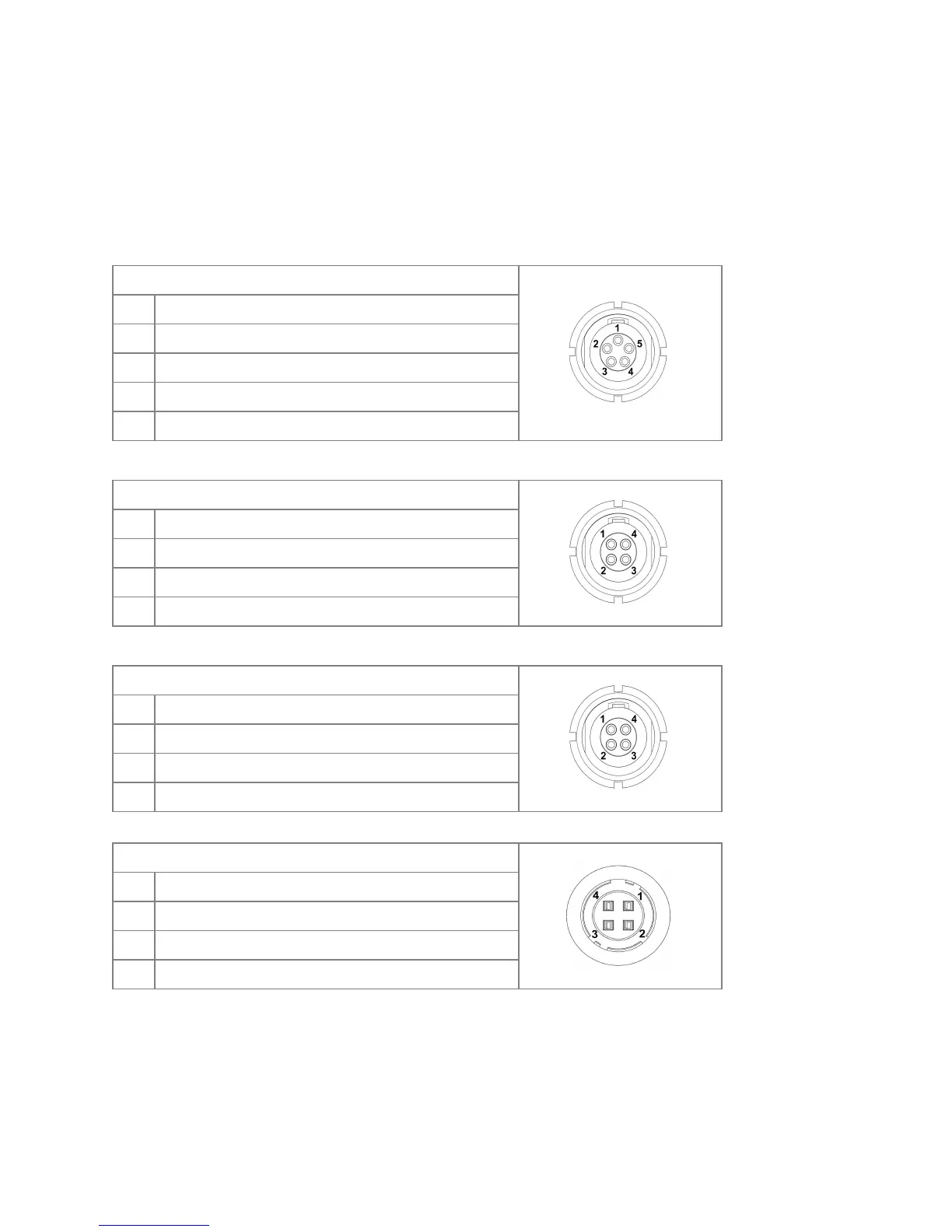
Pin-Outs
Please take special care when making your own cables. While the majority of mis-wirings are
protected against with advanced circuitry, it is NOT possible to protect against every possible
mis-wiring, and therefore damage can be done.
Controller MK3.1 Sockets
WIRED-MODE SOCKET—LM 5-pin 0B
MOTOR BUS SOCKET—LM 4-pin 0B- Can we say LEMO?
3x MOTOR SOCKETS—LM 4-pin 0B
POWER SOCKET—Hirose HR10 4-pin
CAM TRIG (Output) – DO NOT expose to 12V
(currently not used) – DO NOT expose to 12V
Power IN, 5-17V DC (17.5V absolute max)