24
COMPILER TECO/ATI ENDORSEDDATE
14.07.2003
REG. CODE
1-5302-612
MODEL N°
50894
DATE OF ISSUE
07-03
REVISION 00
X
29
30
31
32
A B
C
D
34,69 ÷ 34,74
35,00 ÷ 35,04
25,00 ÷ 25,20
0,040 ÷ 0,074
0,07 ÷ 0,105
0,07 ÷ 0,105
E
F
G
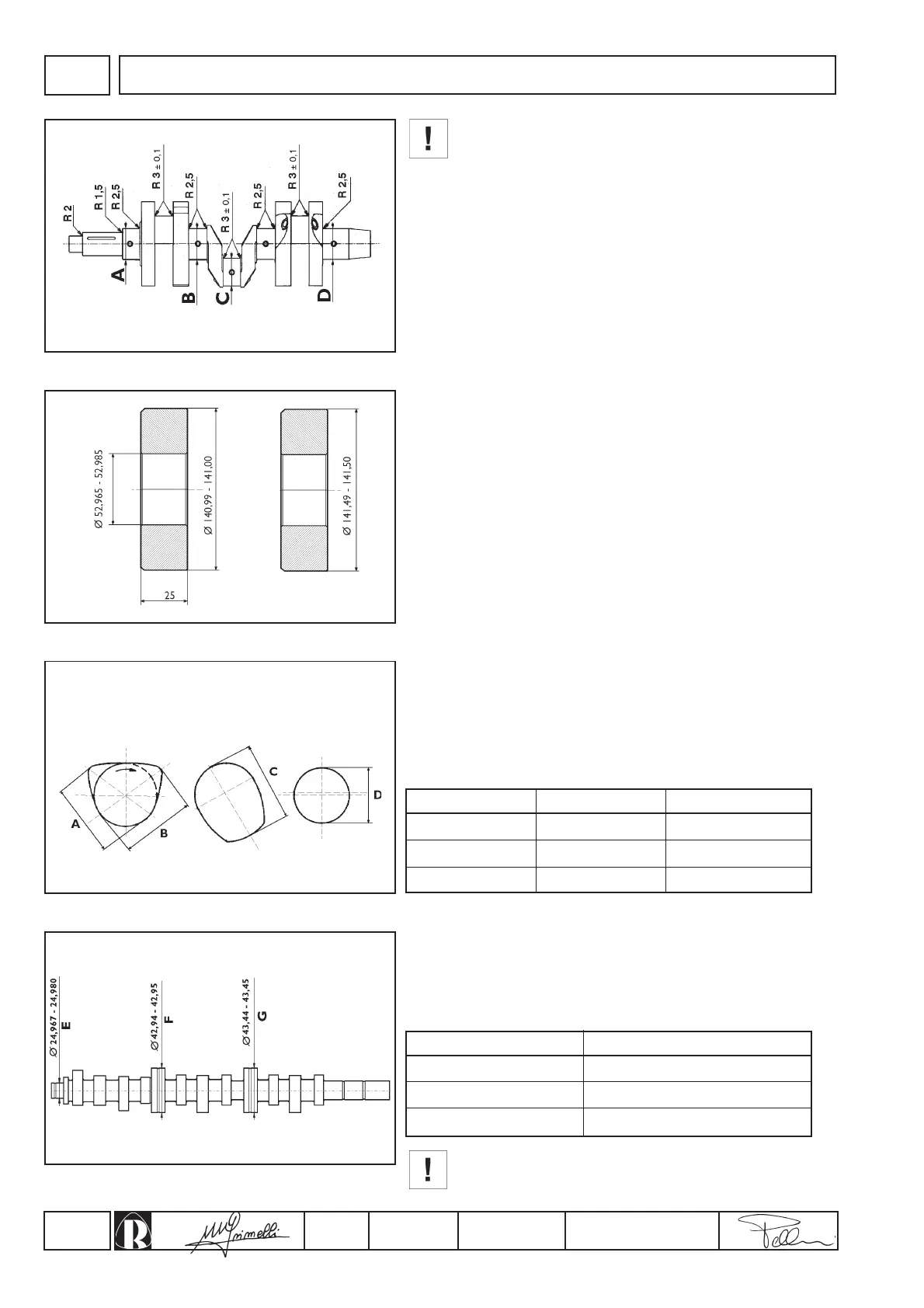
During grinding take care not to remove the shim
adjustment material from the main journal thrust face to
avoid changing the crankshaft end float; also ensure that
the grinding wheel radii are as specified in figure 29 so as
not to create crack initiation sections on the crankshaft.
CHECKS AND OVERHAUL
Measurement Dimensions mmCam
Timing
Injection
Fuel pump
Measurement Clearance mm
Central main bearings
In order to facilitate assembly the central main bearings are of
different external diameters (fig. 30) and are machined with a
bevelled edge to assist their insertion into the crankcase.
Check the dimensions of the shells and renew them if they are
worn or deformed.
Also check the condition of the oil passages and, if necessary,
clean them with paraffin or petrol and dry with compressed air.
Oil seal rings
Check that the rings have not hardened around the internal contact
edge and that they show no signs of cracks or wear.
Camshaft
Check the cams and bearing journals for scoring and wear.
Measure the dimensions and compare them to the values in the
table below and shown if figures 31 and 32.
Camshaft dimensions fig. 31.
Renew the camshaft if the cams or journals show wear in
excess of 0.1mm.
Assembly clearance between the journals and their housings
should be (fig. 32):
inlet/exhaust injection feeding pump
 Loading...