28
COMPILER TECO/ATI ENDORSEDDATE
14.07.2003
REG. CODE
1-5302-612
MODEL N°
50894
DATE OF ISSUE
07-03
REVISION 00
XI
43
44
45
46
INJECTION EQUIPMENT
The difference between the deliveries of the two pumps
when locked must not exceed 0.5 cc.
Also check:
1.That the distance between the injection cams in the rest
position (bottom dead centre) and the pump supporting face is
between 52.8 and 54.4 mm as shown on the data plate;
2.That the stroke of the piston with injection cams in the rest
position (bottom dead centre), to the start of delivery is between
2 and 2.1 mm.
Assembly of injection pumps
If it proves necessary to disassemble the injection pumps they
must be reassembled following the instructions listed below:
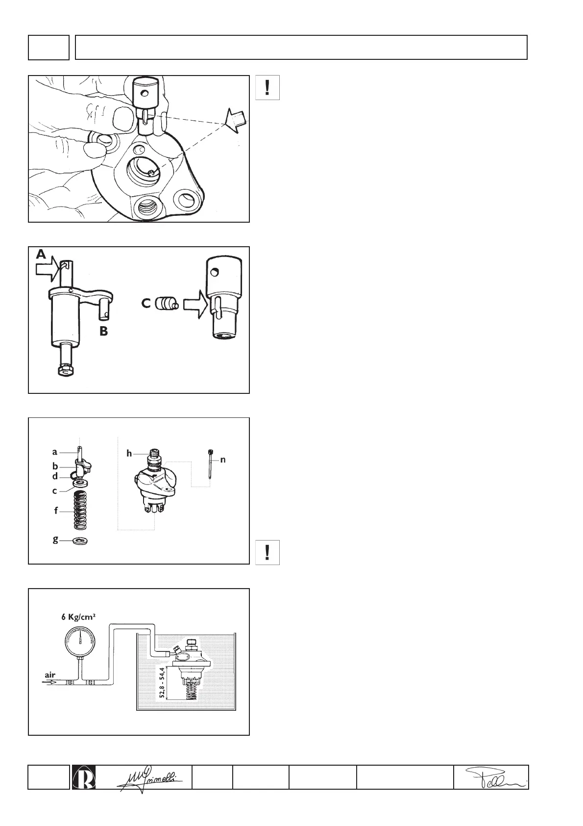
1.Insert barrel into pump casing with the fuel inlet hole aligned
with the feeding connection (fig.43). This is the only possible
position because of the stud on the pump body. Make sure that
the seating face between the barrel and the pump are free of
dirt.
2.Insert delivery valve, copper gasket, spring, washer, filler, O-
ring, and temporarily tighten the delivery connection.
3.Insert plunger, with helical profile (A, fig.44) on the opposite
side of the sleeve pin (B, fig.44), into the internal groove of the
control sleeve (make sure the helical profile is turned towards
the fuel inlet and eccentric pin (C, fig.44).
4.Complete pump assembly with plunger (a, fig.45), control
sleeve (b), upper washer (c), retaining ring (d), spring (f) and
secure all with the spring holder washer (g)
5.Tighten delivery valve holder (h, fig.45) to 4.5 ÷ 5 kgm torque.
6.Check, by compressing the spring through its various work
positions, that the control sleeve (b, fig.45) turns freely and
does not stick or encounter resistance throughout its full stroke;
any irregular movement will give rise to hunting of engine
speeds.
7.Secure the control sleeve using the pin (n, fig.45) screwed into
pump housing.
Always check the injection pump calibration after the
delivery connection (h, fig.45) has been dismantled.
Testing air tightness
Feed pressurized air at 6 Kg/cm² into the fuel sullpy union and
completely immerse the pump in oil or diesel fuel for about 20 ÷ 30
seconds (fig.46); check that no air bubbles are released.
N.B.: Tightness can be checked by compressing the springs to
52.8 ÷ 54.4 mm, which corresponds to the bottom dead centre
working position of the pump.
 Loading...