34
COMPILER TECO/ATI ENDORSEDDATE
14.07.2003
REG. CODE
1-5302-612
MODEL N°
50894
DATE OF ISSUE
07-03
REVISION 00
XIII
73
74
71 72
75
76
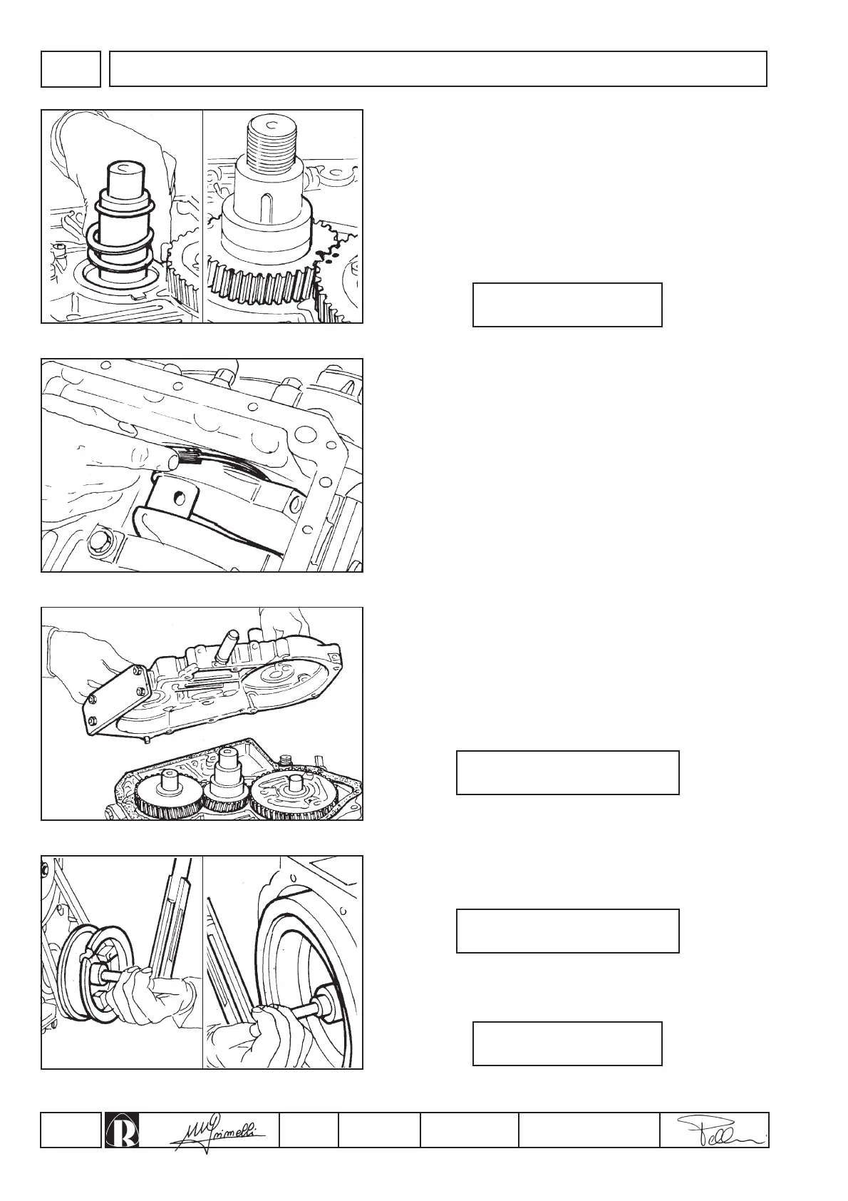
0,10 ÷ 0,25 mm
kgm 2,2 ÷ 2,4 (Nm 21,6 ÷ 23,5)
kgm 32 (Nm 314)
kgm 19 ÷ 22 (Nm 186,5 ÷ 216)
Fit the flywheel-housing and flywheel (fig. 76) and torque the latter
to:
Crankshaft end float
Once the crankshaft has been inserted into the crankcase, fit the
external clearance adjustment ring with the milled grooves facing
toward the timing gear. Also fit the brass shims, the O-ring (fig. 71),
the key, the timing gear - ensuring that the reference marks match
those on the camshaft gear (fig. 72), the pulley, and the washer, and
then tighten the nut securing the pulley.
Use a feeler gauge to check the clearance between the clearance
adjustment ring and the crankshaft (fig. 73); the value must be
within the range:
Pulley and flywheel
Tighten the pulley fixing bolt (fig. 75) to:
Timing cover
Check that the timing references punched on the camshaft and
crankshaft gears are mutually aligned (fig. 72).
Fit the oil seal onto the cover using a normal tubular punch of
appropriate diameter. Mount the cover to the crankcase (fig. 74) after
first inserting a gasket between the facing surfaces; tighten the
fixing screws to:
If the value is different, fit or remove the brass shims mounted
behind the crankshaft gear.
ENGINE ASSEMBLY
 Loading...