MODEL 53515/53615/63515/63615/73515/73615
12
③ Pipeline connection
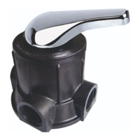
a. As Figure 1-3 shows, install a pressure gauge in water inlet.
b. Install valves A.B.C.D in inlet, outlet, inlet pipeline and outlet pipeline.
Valve D is a sampling valve.
c. Inlet pipeline should be in parallel with outlet pipeline. Support inlet
and outlet pipeline with fixed holder.
Note:
●If making a soldered copper installation, do all sweat soldering
before connecting pipes to the valve. Torch heat will damage
plastic parts.
●When turning threaded pipe fittings onto plastic fitting, do not use
excessive force to make threads misaligned or break valve.
●If the valve belongs to time clock type (63515/73515), there are no