Operation Manual LB2001
Sacher Lasertechnik
GmbH
_____________________________________________________________________________________________________
Adress:
Sacher Lasertechnik GmbH
Rudolf-Breitscheid-Str. 1-5
D-35037 Marburg, Germany
Tel.: +49 (6421) 305-0
Fax.: +49 (6421) 305-299
EMail: contact@sacher-laser.com
Web: http://www.sacher-laser.com
Sacher Lasertechnik, LLC
5765 Equador Way
Buena Park, CA 90620, USA
Tel.: 1-714-670-7605
Fax: 1-714-670-7662
Email: sales@sacher-
laser.com
Page 11
Version:
Preliminary 2011-01-01
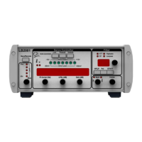
Output (HP): This high pass BNC output is the control signal from the proportional-
integral (P-I) filter and going to the DT1 filter section.
Power switch: This switch is pushed up to | position to turn on AC mains power to
LB2001.
AC Line Power Voltage Selector
Power entry module: The AC power cord must be connected between this instrument
receptacle and a properly grounded mains receptacle. The LB2001 can be configured
to operate with the following AC mains voltages: 100, 120, 220, and 230-240 VAC.
Please carefully read the preceding section Electrical Fuse & Voltage Selection for
instructions on installing the proper fuses and setting the correct AC supply voltage.
PI Filter Output Voltage Limit: This trim-pots determines the integrator voltage rails.
Sweep In 2: Input signals to this BNC connectors are summed into the Output signal.
Sweep In 1: This BNC input allows a low frequency periodic sweep signal to be
added to the output of the LB2001. The input impedance is 1k and the input voltage
range is -10V.. +10V. See Sweep Center and Sweep Span controls discussed below
for more details.
Int. Hold Input: This TTL logic input switches off the error signal input to the P-I
filter and holds the integrator output voltage at its current value
Error Monitor: This BNC output connector is a voltage monitor for the error signal
generated by the input difference amplifier. The DC-coupled error monitor has unity
gain with a nominal output voltage –10V..+10V.