Operation Manual LB2001
Sacher Lasertechnik
GmbH
_____________________________________________________________________________________________________
Adress:
Sacher Lasertechnik GmbH
Rudolf-Breitscheid-Str. 1-5
D-35037 Marburg, Germany
Tel.: +49 (6421) 305-0
Fax.: +49 (6421) 305-299
EMail: contact@sacher-laser.com
Web: http://www.sacher-laser.com
Sacher Lasertechnik, LLC
5765 Equador Way
Buena Park, CA 90620, USA
Tel.: 1-714-670-7605
Fax: 1-714-670-7662
Email: sales@sacher-
laser.com
Page 29
Version:
Preliminary 2011-01-01
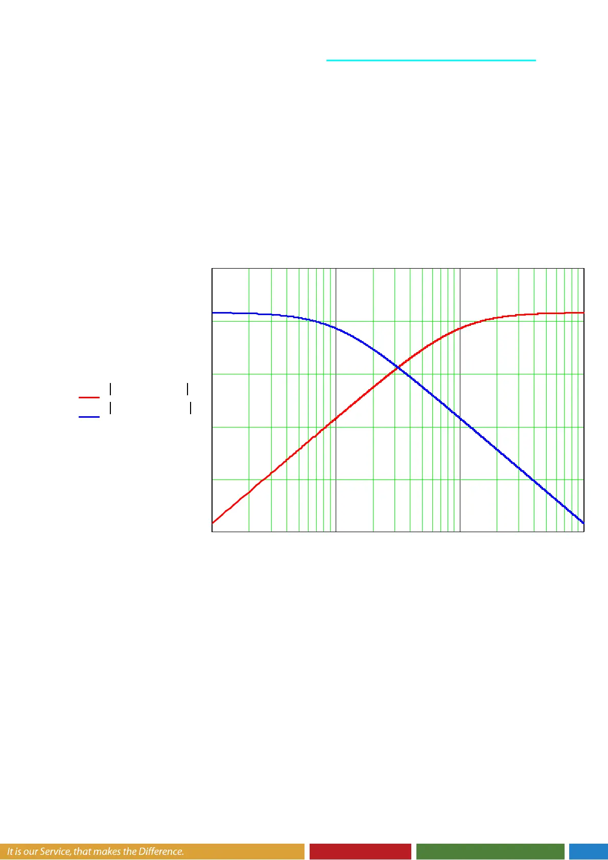
5.6. Frequency Splitter
DT1 and PT1 Filter should act as frequency splitter.
High frequency response of the error amplifier should be directed to the HP Output.
Low Frequency should go to the summing amplifier and then to the LP Output.
The following graph shows both filters in one picture as good a illustration of the frequency
split.
10 100 1 10
3
× 1 10
4
×
40−
30−
20−
10−
0
10
20 log KDT1 63 1000, f, ( )
( )
⋅
20 log KPT1 1 63, 100, f, ( )
( )
⋅
f