Do you have a question about the Sacher Lasertechnik Pilot PC and is the answer not in the manual?
Diagrams illustrating the pinouts and connections for various ports.
Table listing system error codes and their meanings.
Contact information and procedures for obtaining technical assistance.
Detailed description of the PilotPC Laser Driver's capabilities and design.
Explains the different ways a laser diode can be connected to the driver.
Diagram showing the TEC module connected to the TEC controller.
Illustrates safety interlock connection options.
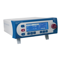
Enumerates and describes the controls and indicators on the front panel.
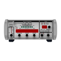
Lists and describes rear panel connectors, including piezo-specific ones.
Explains the four-level tree structure of the device menus.
The top-level menu for navigating device functions.
Menus for primary operational modes like Laser, Temperature, Scan.
Menus for adjusting secondary or protected parameters.
Describes the mode buttons used to access Level II menus.
Information on how user settings are saved in non-volatile memory.
Enables/disables external modulation input.
Configures the external monitor signal as current or power indicator.
Jump to laser setup menu.
Sets the absolute maximum current of the laser diode.
Sets laser diode polarity, referring to Laser Diode Configurations.
Sets compliance voltage, the max input voltage for current source.
Procedure for adjusting the laser power using the jog dial.
Procedure for adjusting the laser temperature using the jog dial.
Menu for configuring temperature control parameters like TEC and T-Watch.
Max. allowed current for the TEC.
Technical specifications for the PilotPC 500 model.
Specifications related to the drive current output and settings for the 4000 model.
Specifications for the TEC output and temperature sensing.
| Brand | Sacher Lasertechnik |
|---|---|
| Model | Pilot PC |
| Category | Controller |
| Language | English |