Operation Manual LB2001
Sacher Lasertechnik
GmbH
_____________________________________________________________________________________________________
Adress:
Sacher Lasertechnik GmbH
Rudolf-Breitscheid-Str. 1-5
D-35037 Marburg, Germany
Tel.: +49 (6421) 305-0
Fax.: +49 (6421) 305-299
EMail: contact@sacher-laser.com
Web: http://www.sacher-laser.com
Sacher Lasertechnik, LLC
5765 Equador Way
Buena Park, CA 90620, USA
Tel.: 1-714-670-7605
Fax: 1-714-670-7662
Email: sales@sacher-
laser.com
Page 18
Version:
Preliminary 2011-01-01
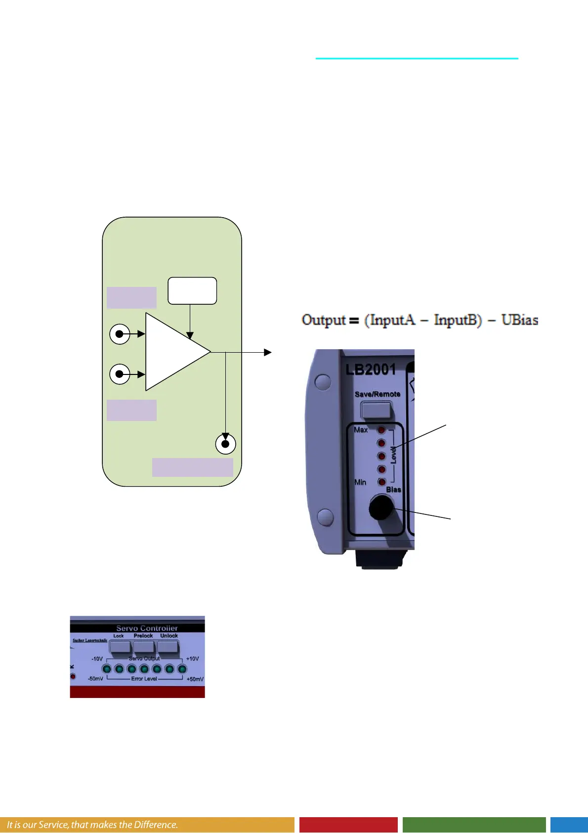
5.2. Input Section
The input section is a difference amplifier
with an adjustable voltage offset (U Bias).
Common-mode voltages ranging from
±10V can be subtracted. Error signals
(observed at the Error Monitor Output) that
exceed the voltage range ±330 mV
saturate the filter amplifier.
A additional levelbar shows the status of
the U Bias Signal.
The U bias signal could be adjusted
from -10V to +10V.
The output signal is related to following
equation.
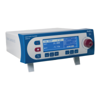
The output level of the input section is displayed on the “Error Level LED Bar”. When
the output level exceeds the range of +/- 50mV the LED bar get flashing.
The U Bias level could be adjusted with the U Bias rotary
switch. The default incremental step size is 0.3 mV. By
pressing the switch the step size is increased to 80 mV
Input -B
Input A
Input Section
U Bias Level
UBias
U Bias Level