Operation Manual LB2001
Sacher Lasertechnik
GmbH
_____________________________________________________________________________________________________
Adress:
Sacher Lasertechnik GmbH
Rudolf-Breitscheid-Str. 1-5
D-35037 Marburg, Germany
Tel.: +49 (6421) 305-0
Fax.: +49 (6421) 305-299
EMail: contact@sacher-laser.com
Web: http://www.sacher-laser.com
Sacher Lasertechnik, LLC
5765 Equador Way
Buena Park, CA 90620, USA
Tel.: 1-714-670-7605
Fax: 1-714-670-7662
Email: sales@sacher-
laser.com
Page 14
Version:
Preliminary 2011-01-01
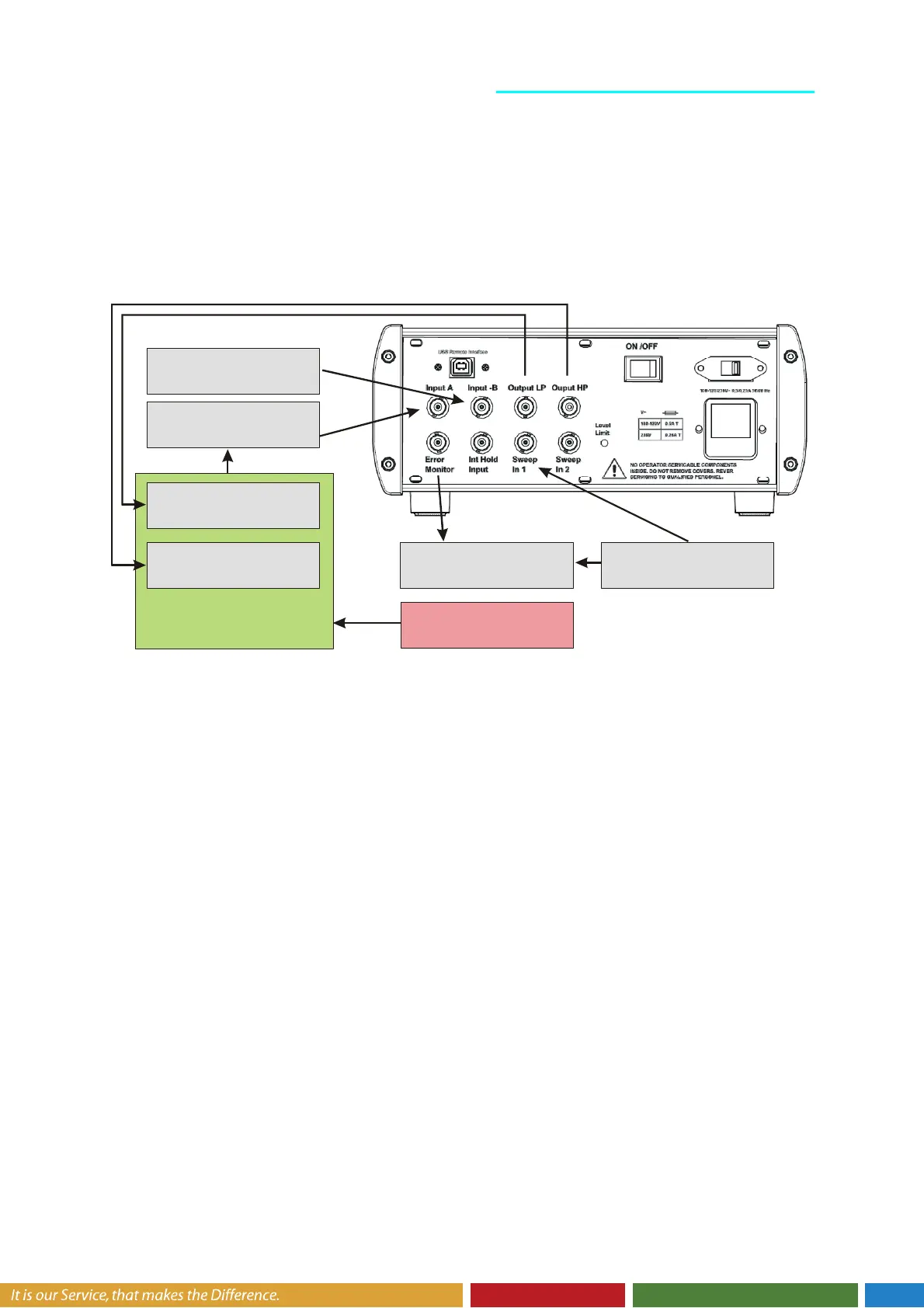
The A and -B inputs can be used together with differential signals to remove common-mode
noise and systematics. Single-ended signals can also be connected, as shown by connection
1a, by simply leaving the unused channel unconnected, or, as depicted by connection 1b, by
attaching a stable voltage source that generates an external set-point voltage. Alternatively,
the Input Offset knob can provide DC offset to the detector signals. To invert either
differential or single-ended signals, use the Polarity button to reverse the connections.
Function Generator (optional)
generates Sweep Signal
Y-Channel X-Channel
Monitors Error Signal
Ocilloscope (recommended)
Detector
Photo Diode
Atomic Resonance
Setpoint Generator (optional)
Precision Voltage Source
Digital to Analog Converter
Transducer / Driver (LP)
Piezoelectric Transducer
Transducer / Driver (HP)
Laser Diode Injection Current
Controlled Parameter
Optical Frequency
External Perturbations
Temperature Drift
Accoustic Noise
1a
1b
3
LB2001 Output to transducer input: To close the feedback loop, an electrically tuned
transducer is necessary for varying the controlled parameter. (2a) A piezoelectric
transducer (PZT) to which a cavity mirror is mounted can tune the wavelength of a
laser. Typically, the LP output of the LB2001 does not interface with the transducer
directly but instead provides the input to an amplifier system that conditions the
control signal to properly drive the transducer. For the PZT discussed above, the
control signal from the LB2001 Output will usually feed a high-voltage amplifier that
connects to the PZT. Be careful not to exceed any input voltage limits of the
transducer. (2b) Variation of the laser diode injection current which tunes the
wavelength of a laser. Typically, the HP output is feed to a bias-tee which provides
modulation to the laser current. Be careful not to exceed any input voltage limits of
the bias-tee.
If necessary, the Output voltage of the LB2001 can be limited by setting the Output Voltage
Limit trim pots located on the rear panel. See section Setting Output Voltage Limits in
Chapter 3 for more details.
LB2001 Error Monitor output to oscilloscope: The Error Monitor allows the user to
view the actual error signal that is being processed by the P-I filter. Since integral
feedback forces the error signal to zero voltage, the parameter that is being
controlled will assume whatever value corresponds to zero error (equal to zero volts).
Observing the Error Monitor enables the user to adjust offsets so that the locking