Operation Manual LB2001
Sacher Lasertechnik
GmbH
_____________________________________________________________________________________________________
Adress:
Sacher Lasertechnik GmbH
Rudolf-Breitscheid-Str. 1-5
D-35037 Marburg, Germany
Tel.: +49 (6421) 305-0
Fax.: +49 (6421) 305-299
EMail: contact@sacher-laser.com
Web: http://www.sacher-laser.com
Sacher Lasertechnik, LLC
5765 Equador Way
Buena Park, CA 90620, USA
Tel.: 1-714-670-7605
Fax: 1-714-670-7662
Email: sales@sacher-
laser.com
Page 16
Version:
Preliminary 2011-01-01
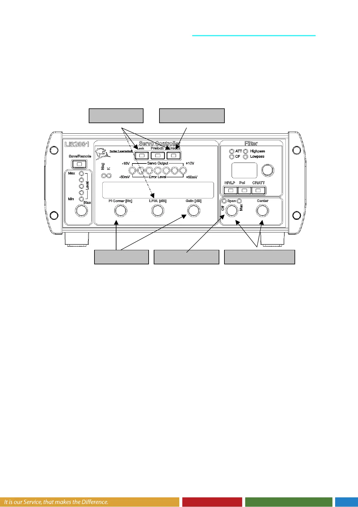
Acquire lock: The Acquire toggle switch offers two gain settings for turning on the
feedback control. When acquiring lock, sometimes it is helpful to limit the DC gain of the
integrator. The LFGL position is an intermediate lock mode that applies the P-I filter with a
low frequency gain limit. The LF Gain Limit front panel switch determines the setting for this
gain limit, and is typically only set once for a specific servo application.
The Lock On position disables the low-frequency gain limit and applies the full integrator
gain to the output. Most servo systems should be locked in this position to minimize DC
errors. When correctly locked, the Error Monitor signal should be very near zero volts, and
the LED indicator light should be green (see Figure 6 for more details.)
Turn off sweep: If the output was swept to find the lock point, then it is good practice to
turn the Sweep Span knob to Off after acquiring lock. This completely disables the sweep
signal, and prevents the feedback from working “overtime” to correct the error induced by the
sweep signal.
Adjust filter: The P-I Corner frequency can be tuned for optimal performance and stability.
Once optimized, it rarely needs to be revisited. However, re-tuning the Gain knob is done
fairly often to find the maximum gain setting. A common procedure to is to increase the gain
until an oscillation is observed on the Error Monitor, and then reduce the gain until the
oscillation just barely stops.
3. Aquire Lock
4. Turn Sweep
2. Find Locking
1. Reset Integrator
5. Adjust Filter