Operation Manual LB2001
Sacher Lasertechnik
GmbH
_____________________________________________________________________________________________________
Adress:
Sacher Lasertechnik GmbH
Rudolf-Breitscheid-Str. 1-5
D-35037 Marburg, Germany
Tel.: +49 (6421) 305-0
Fax.: +49 (6421) 305-299
EMail: contact@sacher-laser.com
Web: http://www.sacher-laser.com
Sacher Lasertechnik, LLC
5765 Equador Way
Buena Park, CA 90620, USA
Tel.: 1-714-670-7605
Fax: 1-714-670-7662
Email: sales@sacher-
laser.com
Page 8
Version:
Preliminary 2011-01-01
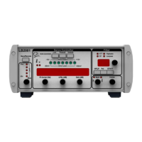
The detailed functions are:
Bias voltage level. The position of the LED signal indicates the position of the bias
voltage level relative to the +/-10V operation range of the LB2001
Save Switch remote indicator. When “Save” is pressed all settings will be stored in a
EEPROM
Unit indicator for PI Corner frequency
Acquire Buttons: These buttons are used to acquire lock. Table 2 shows
the function for each switch position.
The position of the Green LED signal indicates the position of the integrator level
relative to the +/-10V operation range of the LB2001.
The position of the Red LED signal indicates the position of the Error level relative to
a +/-50mV voltage range. The locked system should always be in the the +/-50mV window.
Filter parameter display
Display indicators. Shows which parameter could be adjusted with the rotary switch.
Filter Frequency Adjustment: Depending on the setting of the Low Pass / High Pass
Selection Switch, this knob adjusts
The low pass filter frequency of the high pass filter path