14
English
1
•
2
•
3
•
4
•
Fig.15
☞
Fig.13
Fig.14
6
3
4
•
2
1
3
4
2
1
•
•
•
•
•
•
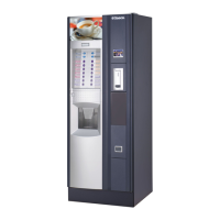
4.12 Assembling Saeco Card system
- Connect the antenna cable ref. 1 (Fig. 13) to the clamp on the universal
module ref. 2 (Fig. 13).
NOTE: Take care when performing this procedure. Make sure
that the metal chip ref. 3 (Fig. 13) is underneath the
strain relief ref. 4 (Fig. 13) and that the screw head
and washer ref. 5 (Fig. 13) make contact with the
center conductor ref. 6 (Fig. 13).
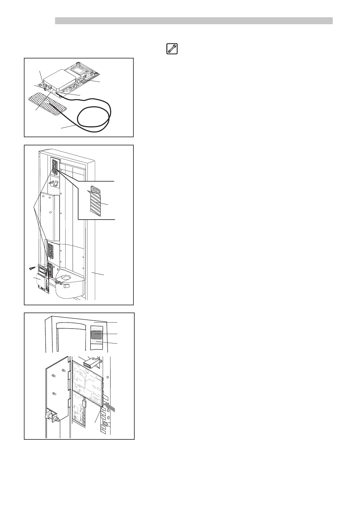
- Install the universal module ref. 2 (Fig. 14) inside the front door ref. 1
(Fig. 14) using the supplied screws.
- Place the antenna ref. 3 (Fig. 14) in one of the three positions on the front
door ref. 1 (Fig. 14). Use double-sided adhesive to firmly secure the an-
tenna in place.
- Apply the adhesive guard ref. 4 (Fig. 14), supplied with the kit, over the
antenna. Make sure the antenna is completely covered and protected.
- On the front door exterior ref. 1 (Fig. 15), apply the adhesive label ref. 2
(Fig. 15) in correspondence with the antenna ref. 3 (Fig. 15) on the inte-
rior. The label indicates where to hold the Card to communicate with the
Saeco Card system.
- Using the supplied flat cable, connect the universal module ref. 2 (Fig.
14) to the 20-pin connector ref. 4 (Fig. 15) on the electronic board.
5
 Loading...