Functional unit workshop service VHF 5000 System
3-12
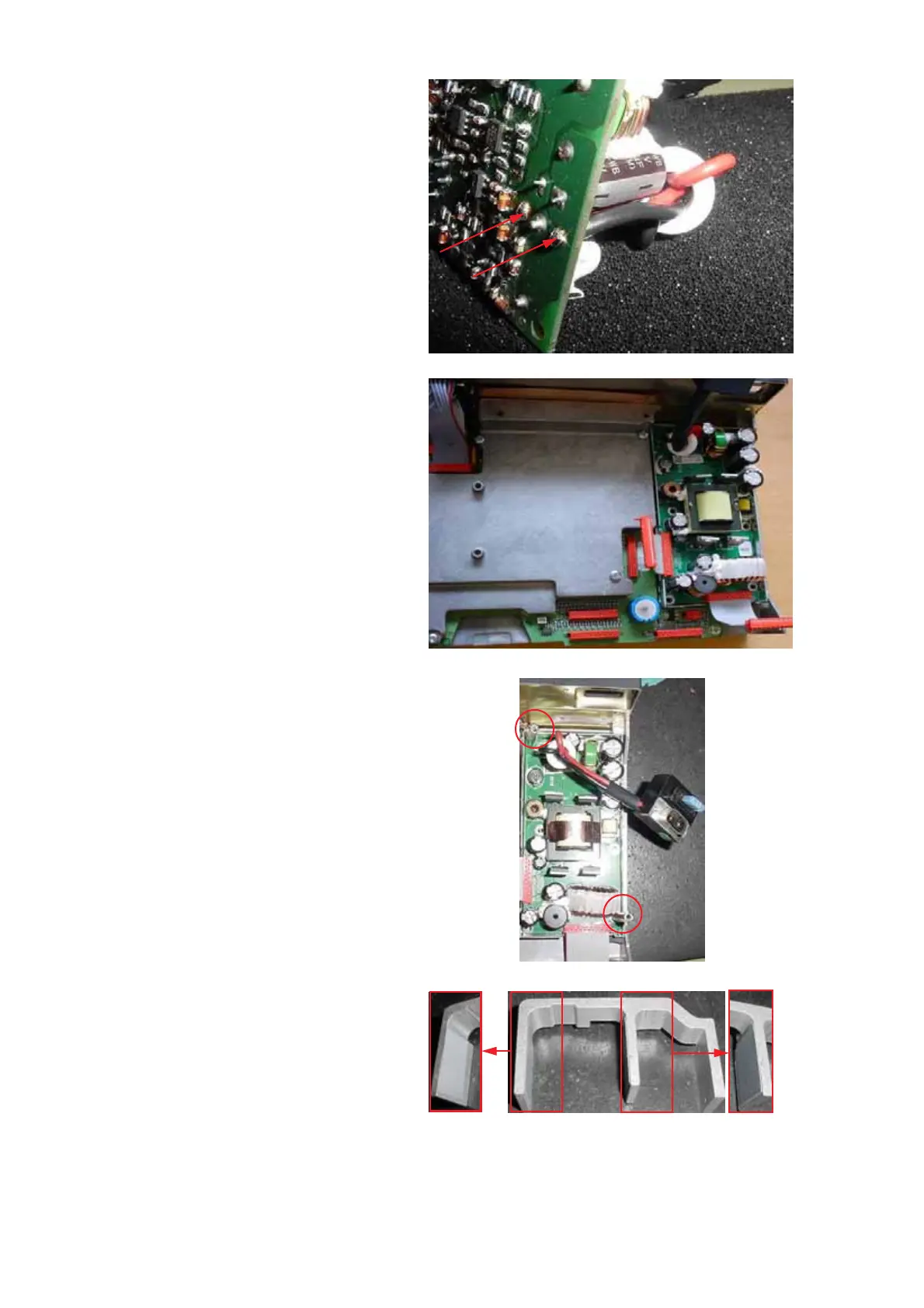
Note: Cut the end stubs of the wires on the soldering
side of the pcb to a length not exceeding 3mm.
1007
Installing:
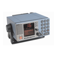
• Position the new PSU module in the chassis.
• Install the screws and the two (2) stand offs which
were removed in step 4.
Note: When tightening up the screws and stand
offs exercise care not to over tighten to avoid
damaging the threads in the chassis.
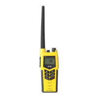
• Verify that the two insulation sheets at the E-profile
are in good condition. If damaged in any way they
should be replaced.
Fig. 10
Fig. 11
Fig. 12
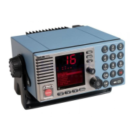
Fig. 13